GRAPHICS 1208s R9000893 R9000896 OWNER'S MANUAL
BARCO PROJECTION SYSTEMS GRAPHICS 1208s R9000893 R9000896 OWNER'S MANUAL Date : 220197 Art. No.
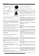
Due to constant research, the information in this manual is subject to change without notice. Produced by BARCO NV, January 1997. All rights reserved. Trademarks are the rights of their respective owners.
Table of Contents Table of contents ........................................................................................................................................................................... i Safety instructions ..................................................................................................................................................................... 1-1 On safety ......................................................................................................
Table of Contents Blanking Adjustments ........................................................................................................................................................ 6-15 Convergence Adjustment .................................................................................................................................................. 6-16 Service mode ..............................................................................................................................
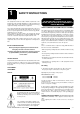
Safety Instructions 1 SAFETY INSTRUCTIONS Notice on Safety This equipment is built in accordance with the requirements of the international safety standards EN60950, UL 1950 and CSA C22.2 No.950, which are the safety standards of information technology equipment including electrical business equipment.
Safety Instructions A. Mains lead (Power cord) with CEE 7 plug: qualified service personnel under the following conditions: The wires of the mains lead are colored in accordance with the following code. a. When the power cord or plug is damaged or frayed. b. If liquid has been spilled into the equipment. Green and yellow: Blue: Brown: earth (safety earth) neutral line (live) B. Power cord with ANSI 73.11 plug: The wires of the power cord are colored in accordance with the following code.
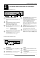
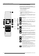
Location and Functions of Control 2 LOCATION AND FUNCTION OF CONTROLS REAR PANEL TERMINOLOGY PORT 1 (VIDEO) PORT 4/5 (RGB - HV) PROJECTOR MODE PORT 6 REMOTE COMMUNICATION PORT 3 R 1 1 2 3 2 B 3 OFF ON PORT 2 (S-VIDEO) OFF ON 75 ohm 75 ohm 4 5 6 Communication Port (800 peripherals) * allows communication between the RCVDS switcher and the projector. * allows connection of a remote IR receiver unit to the projector. 7 Projector Pilot Lamp : indicates the status of the projector.
Location and Functions of Control b. RCU control panel terminology This remote control includes a battery powered infrared (IR) transmitter that allows the user to control the projector remotely. This remote control is used for source selection, control, adaptation and set-up. It includes automatic storing of : - picture controls (Brightness, Sharpness,....
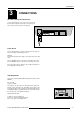
Connections 3 CONNECTIONS AC Power (mains) Cord Connection Use the supplied power cord to connect your projector to the wall outlet. Plug the female power connector into the male connector at the backside of the projector. V NOM 120/230 Volt I MAX 7/5Amp FREQ 50/60Hz IR RS232 IN RS232 OUT RS232 OUT REMOTE RS232 IN IR REMOTE 685 Power Check Power voltage indication on sticker on the back side of the projector. The power voltage is indicated by the art. no.
Connections When starting up the projector, with the power switch or via the stand-by key, the projector can start up in two ways if the "CRT run in" cycle option is switched OFF. - full white image (projector warm up) or - immediately image display. The way of starting up can be set in the service mode. Start up with full white image. The next menu will be displayed for 30 seconds. PROJECTOR WARM UP a. Start up with warm up period. A FULL WHITE PATTERN WILL BE GENERATED FOR 20 MINUTES.
Connections Connecting a Composite Video source to port 1. Composite video signals from a VCR, OFF air signal decoder, etc.. PORT 1 (VIDEO) PORT 4/5 (RGB - HV) PROJECTOR MODE PORT 6 REMOTE COMMUNICATION PORT 3 R G POWER/MAINS GREEN : operational RED : stand-by Comp/H sync V sync OFF ON PORT 2 (S-VIDEO) OFF ON 75 ohm 75 ohm B Composite video to next projector or to a monitor Video input selection : with the RCU or the build in RCU : press digit button 1 TV tuner, e.g.
Connections Connecting a RGB Analog source to port 3. Connect your RGB source via an interface to Port 3. Always use an interface when a computer and local monitor have to be connected to the projector.
Connections Connecting a RGB Analog source with Tri-level sync to port 4/5. (option) PORT 1 (VIDEO) PORT 4/5 (RGB - HV) Comp/H sync V sync PORT 6 REMOTE COMMUNICATION PORT 3 RGB analog input terminals with Tri level sync input or with Tri-level sync on green. The projector detects automatically where the sync signal is located.
Connections PERIPHERAL EQUIPMENT Connecting a RCVDS 05 switcher to the BARCOGRAPHICS 1208s - Up to 20 inputs with the RCVDS 05 switcher and up to 90 inputs when 10 RCVDS switchers are linked via the expansion modules. - Serial communication with the projector.
Controlling 4 CONTROLLING Caution : Do not display a stationary image with full brightness and contrast for longer than 20 min., otherwise you risk damage to the CRT's. Battery installation in the RCU. A new battery (not yet installed to save the battery life) is delivered inside the plastic bag with the power cord. Before using the RCU, follow the battery installation procedure. Remove the battery cover on the backside of the RCU by pushing the indicated handle a little to the bottom of the RCU.
Controlling The BARCOGRAPHICS 1208s can be controlled with a. the RCU b. the hardwired RCU (cable not included) c. the built-in RCU (local keypad) c) RCU used in a hardwired configuration. RS232 IN RS232 OUT REMOTE IR The procedure and results of controlling the projector with either of these RCU options is essentially the same.
Controlling With the digit buttons on the RCU, it is possible to select input sources, Video, S-Video, RGsB or RGBS, RG3sB or RGB3S. How to display a projector address? Press the ADDRESS key (recessed key on the RCU) with a pencil. The projector's address will be displayed in a 'Text box'. This text box When a valid and available source is selected, there will be information displayed on the screen about that source (if "Text" is on).
Controlling Analog Picture Controls The analog picture controls can be adjusted with the RCU. The control keys are located on the lower right side of the key panel of the RCU and indicated with the name of the control and an icon. When an analog picture control is pressed, a text box with bar scale and the function name of the control, e.g. 'brightness...' appears on the screen (only if 'TEXT' is ON). The length of the bar scale indicates the current memorized setting for this source.
Start Up of the Adjustment Mode 5 START UP OF THE ADJUSTMENT MODE Adjustment Mode All picture geometry and convergence adjustments are made while in the 'Adjustment mode'. Press the ADJUST key to enter the 'adjustment mode'. You are now in the 'Adjustment mode'. The Control stick is used to make menu selections and also vertical and horizontal adjustments. The ENTER and EXIT keys are used to move forward and backward through the menu structure.
Start Up of the Adjustment Mode Some items in the Adjustment mode are password protected. While selecting such an item, the projector asks you to enter your password. (Password protection is only available when the password DIP switch on the controller module is in the ON position. Contact a BARCO authorized technician when no password is requested during the adjustment procedure and password protection is desired.) Your password contains 4 digits. Enter the digits with the numeric keys on the RCU.
Random Access Adjustment Mode 6 RANDOM ACCESS ADJUSTMENT MODE Starting-Up the Random Access Adjustment mode. Push the control stick forward or backward to highlight "RANDOM ACCESS" and then press ENTER. Some items in the Random access mode are password protected (when the password function is enabled). Enter your password to continue. All other password protected items are now also available if you stay in the adjustment mode.
Random Access Adjustment Mode From next page From next page H SIZE V LINEARITY TOP V SIZE BOTTOM BLANKING LEFT RIGHT COARSE ADJUSTMENT RANDOM ACCESS ADJUSTMENT MODE CONVERGENCE RED ON GREEN HORIZONTAL SIDES BLUE ON GREEN VERTICAL CORNERS FINE ADJUSTMENT SETUP PATTERN SELECTION GREEN ONLY RED ON GREEN BLUE ON GREEN RED FOCUSING GREEN BLUE RED GREEN BLUE COLOR SELECT RED AND GREEN BLUE AND GREEN RED AND BLUE ORBITING CONTRAST MODULATION SOFT EDGE CORRECTION 6-2 5975847 BARCOGRAPHICS 1208S 22
Random Access Adjustment Mode Selecting Setup Pattern If an external source is connected to the projector, this menu will be displayed. Push the control stick forward or backward to highlight the desired setup pattern and then press ENTER. Genlocked pattern : internally generated cross hatch pattern, locked on the external source.
Random Access Adjustment Mode Random access adjustment mode selection menu. This is the main menu for the Random Access adjustment mode. Through this menu, the following adjustments and features are accessible : - Picture Tuning Enhanced Blue (only for RGB) Sync slow/fast(video/s-video) Color Balance - Focusing - Geometry - Convergence - Color select And also Orbiting, Contrast modulation and Soft Edge if these options are installed.
Random Access Adjustment Mode Sync Fast/Slow Adjustment The sync function is used to minimize horizontal jittering or tearing at the top to the displayed image. Highlight SYNC by pushing the control stick forward or backward and press ENTER to toggle between FAST and SLOW. Note: SYNC is normally used in the SLOW position. For Video and S-Video the sync is automatically set to FAST.
Random Access Adjustment Mode Port 2 : Video or S-Video Port 2 can be used as a Video or S-Video input. Highlight Port 2 by pushing the control stick forward or backward and press ENTER to toggle between VIDEO and S-VIDEO. PICTURE TUNING COLOR BALANCE PORT2 : S-VIDEO LINE DOUBLER : ON Select with or to accept to return. Line Doubler (option) Line doubling is only possible for Video, S-Video, Component Video images on standard line frequency and RGB signals on 15 kHz.
Random Access Adjustment Mode Focusing Before starting the 'focusing' adjustment, be sure the lenses are correctly focused. Push the control stick forward or backward to select 'Focusing' and press ENTER. RANDOM ACCESS ADJUSTMENT MODE PICTURE TUNING GEOMETRY CONVERGENCE FOCUSING COLOR SELECT ORBITING CONTR. MODULATION SOFT EDGE ENTER continues to the Focusing color select menu. EXIT returns to Internal Crosshatch Selection or Setup Pattern Selection menu. ADJUST returns to operational mode.
Random Access Adjustment Mode Geometry Adjustments The geometry adjustments have to be done only on the green image. These adjustments are automatically implemented for the other color images : Left-right (EW) and Top-Bottom Corrections, Blanking, Horizontal Amplitude, Vertical Amplitude, Vertical Linearity and Horizontal Phase. Highlight GEOMETRY by pushing the control stick forward or backward and press ENTER to display the geometry menu.
Random Access Adjustment Mode Raster Shift Adjustment The green raster must be centered both horizontally and vertically on the center of the CRT surface. To center the green raster, look into the green lens and use the control stick to move the raster. GEOMETRY H PHASE RASTER SHIFT LEFT-RIGHT (E-W) LEFT SIDE CORRECTION TOP-BOTTOM (N-S) H SIZE V LINEARITY V SIZE BLANKING CAUTION It is necessary to look into the lenses to perform these adjustments.
Random Access Adjustment Mode Left-Right (east-west) Adjustments Left-right adjustments affect only the vertical lines of the projected image. Only the green image is displayed while making left-right adjustments. The red and blue images will automatically be corrected in the same manner. Convergence corrections are automatically disabled for the duration of these adjustments.
Random Access Adjustment Mode Seagull correction Use this correction only if, after adjusting the vertical lines with the side bow or side keystone, still a 'S' deformation is visible on the left and the right side of the image. The default value on the bar scale for this correction is 50. Push the control stick forward or backward to highlight SEAGULL CORRECTION on the Left-Right menu and then press ENTER.
Random Access Adjustment Mode Top-Bottom (north-south) Adjustments GEOMETRY Top-Bottom and center adjustments affect only the horizontal lines of the projected image. To start up the Top-Bottom and center corrections, follow the next procedure : Push the control stick forward or backward to highlight TOP-BOTTOM (N/S) on the geometry menu and then press ENTER.
Random Access Adjustment Mode Seagull Correction Use this correction after the image has been adjusted with top and bottom bow and keystone. If still a deformation (like a seagull) on top and bottom of the image is visible, proceed to the seagull correction. Due to interaction, it is possible that the top and bottom bow have to be readjusted after adjusting the seagull correction to obtain an improved image. The default value on the bar scale of this correction is 50.
Random Access Adjustment Mode Vertical Linearity Adjustment The vertical linearity adjustment function corrects for vertical nonlinearities which extend from the center of the image to the top and bottom of the image. Push the control stick forward or backward to highlight V LINEARITY on the Geometry menu and then press ENTER.
Random Access Adjustment Mode Blanking Adjustments Blanking adjustments affect only the edges of the projected image and are used to frame the projected image on to the screen and to hide or black out unwanted information (or noise). A 0% on the bar scale indicates no blanking.
Random Access Adjustment Mode Convergence Adjustment Convergence adjustments affect both the horizontal and vertical lines of the setup pattern. These adjustments are performed on the red image while superimposed on the green image and then on the blue image while superimposed on the green image. Start with the Coarse convergence adjustments and finalise with the Fine convergence adjustment. RANDOM ACCESS ADJUSTMENT MODE PICTURE TUNING GEOMETRY CONVERGENCE FOCUSING COLOR SELECT ORBITING CONTR.
Random Access Adjustment Mode Vertical corners Highlight 'Vertical corners' and press ENTER to start the adjustment. To make a coarse adjustment of the red or blue horizontal lines in zone 10, 14, 18 and 22 simultaneously. Select with or then to return.CONVERGENCE COARSE HORIZONTAL SIDES VERTICAL CORNERS Select with or then to return. Hint : - adjust until the red or the blue horizontal lines are on the green lines or as close as possible to the green lines.
Service Mode 7 SERVICE MODE Starting up the Service mode. Use the control stick to highlight 'Service' and then press ENTER. ADJUSTMENT MODE Some items in the Service mode are password protected (when the password function is active). Enter your password to continue. All other password protected items are now also free available if you stay in the adjustment mode. ENTER continues to the Service Mode main menu. EXIT returns to the Operational mode. The service items are combined in two service menus.
Service Mode Identification Highlight 'Identification' with the control stick and press ENTER. SERVICE MODE IDENTIFICATION COPY A BLOCK DELTE A BLOCK DELETE ALL BLOCKS CHANGE PASSWORD CHANGE LANGUAGE RUN TIME SET TO MIDPOSITION CONVERGENCE MID DYNAMIC ASTIGMATISM The 'Identification' screen gives information concerning : - projector address. To change the address of your projector, contact a qualified service technician. - software version. MORE... Select with or then to return.
Service Mode Deletion of blocks This item is password protected. The delete function is used to clear all data (settings) from an adjustment block. A delete can be given : - block by block or - for all blocks. Deleting block by block The delete a block function deletes the settings of a selected block. Highlight 'Delete a block' with the control stick and press ENTER. Push the control stick forward or backward to select the desired adjustment block. Press ENTER to delete the selected adjustment block.
Service Mode Change password This item is password protected. Highlight 'change password' with the control stick and press ENTER. The current password is displayed. The new password must consist of 4 digits between 0 and 9. Push the control stick to the left or to the right to select the digits to be changed. Use the numeric keys to enter the new digits. Press ENTER to save the new password. Before saving the new password, a confirmation screen will be displayed.
Service Mode Set to midposition Item is password protected. Highlight 'set to midposition' with the control stick and press ENTER to set all settings to their midposition. A confirmation menu will be displayed first. SERVICE MODE IDENTIFICATION COPY A BLOCK DELTE A BLOCK DELETE ALL BLOCKS CHANGE PASSWORD CHANGE LANGUAGE RUN TIME SET TO MIDPOSITION CONVERGENCE MID DYNAMIC ASTIGMATISM MORE... ENTER will set all settings to their midposition.
Service Mode When undo is pressed all convergence settings are reset to the previous settings. Dynamic Astigmatism (spot shape adjustment) The spot shape adjustments correct the spot shape in 8 different areas on the screen and that for the three colors separately. The spot shape is adjusted according to the axial axises and the diagonal axises when using the arrow keys on the RCU. 1 3 2 4 5 7 6 These adjustments have to be done on a dot pattern (e.g.
Service Mode Use the up and down arrow keys for the diagonal astigmatism adjustment and the left and right arrow keys for the axial astigmatism adjustment. Press ENTER to continue selecting a new area. The adjustment direction (axial or diagonal) and adjustment value are given in a text box on the screen. When all areas are adjusted, press EXIT to return to the service main menu. G2 Adjust Item is password protected. Highlight 'G2 adjust' with the control stick and press ENTER to continue.
Service Mode Projector Warm Up Highlight 'Projector Warm Up' by pushing the control stick forward or backward and press ENTER to select the projector warm up menu. SERVICE MODE G2 ADJUSTMENT GAMMA CORRECTIONS CRT RUN IN CYCLE PROJECTOR WARM UP CRT DRIVE MODE MORE... The ON/OFF option can be toggled with the ENTER key. Select with or then to return.PROJECTOR WARM UP When in the ON position (and the CRT run in cycle is OFF), the projector can start up with a warm up period of 20 minutes.
Messages, warnings and failure codes 8 MESSAGES, WARNINGS AND FAILURE CODES SOURCE 01 Fh= 15.6 kHz Fv= 050 Hz SOURCE 01 Fh= 15.6 kHz Fv= 050 Hz enter password xxxx When selecting a new source, information about this source will be displayed on the screen. Source number, horizontal and vertical frequencies of the displayed source. WARNING : source not available WARNING : Announcement of the selected source.
Messages, warnings and failure codes WARNING : Projector will switch to 'stand-by' when the RCVDS is no longer available. FAILURE RCVDS communication error Serial communication error between RCVDS800 and projector. WARNING : invalid frequency input The entered frequency or applied frequency of the source is out of the projector's range. FAILURE RWI communication error Hardware failure. Call a qualified service technician.
Options 9 OPTIONS IR Receiver 800 RCVDS 05 Source Selector This infrared receiver unit makes it possible to control the BARCOGRAPHICS 1208S from another room. There is a communication line with cable between the IR receiver and the projector or the RCVDS05. The control information from the RCU can now be sent to this IR receiver. The IR receiver 800 displays the selected source on a 7-segment display. Order number : R9827515 Hardwired RCU.
Options MAGIK Interface Ceiling Mount kit CM100 This heavy duty Ceiling Mount Kit enables the projector to be installed in any ceiling mount application. A heavy duty pulley system facilitates installation and maintenance. order number : R9827341 Orbiting Kit Static pictures are very often shown on large screen projectors, especially in process control and presentation applications.
Orbiting A ORBITING Orbiting (option) Static pictures are very often shown on large screen projectors, espectially in process control and presentation applications. Due to the fact that the same picture information is shown for a long period on the same place, picture tubes can be damaged by 'local burn-in'. Adjustment procedure : The orbiting path is automatically added to the Random access adjustment mode menu when installed. Press ADJUST to enter the adjustment mode and select Random.
Orbiting Orbiting Speed Toggle (only in MASTER Orbiting) Highlight 'SPEED : SLOW' with the control stick and press ENTER to set the ORBITING SPEED to Fast. Highlight 'SPEED : FAST' with the control stick and press ENTER to set the ORBITING SPEED to Slow ENTER continues to Set up Orbiting EXIT returns to path selection menu ADJUST returns to operational mode.
Orbiting Adjustment procedure multiple projector installations : Inportant : to allow corrections in the deviation alignments of the slave projectors, never adjust the deviations of the master projector to its maximum. Default setting of the Master projectorn see 'Stand-Alone projector'. Highlight 'ADJUST DEVIATION' by pushing the control stick forward or backward and press ENTER.
Adjustment Blocks and Source Numbers 90-99 B ADJUSTMENT BLOCKS AND SOURCE NUMBERS 90 - 99 Adjustment Blocks (memory blocks) As the projector is digitally controlled, all geometry and convergence adjustments are stored in the projector’s memory as numeric values. These numeric values are used to control digital potentiometers which in turn, control the projector.
Insert Card INSERT CARD " 5975847 BARCOGRAPHICS 1208S 220197 RCU RCU INPUT SOURCES PROJECTOR 1 2 3 4 5 6 7 INPUT SOURCES PROJECTOR 1 P2 3 4 5 6 7 INPUT SOURCES RCVDS INPUT SOURCES RCVDS 1 2 3 5 6 7 8 9 1 2 3 5 6 7 8 9 10 10 P i-1