Solaris LC40 Owners Manual R9004120 (Events) R9004125 (Media) R5976672/04 13/01/2005
Barco nv Media Noordlaan 5, B-8520 Kuurne Phone: +32 56.36.89.70 Fax: +32 56.36.83.86 E-mail: media@barco.com Visit us at the web: www.barco.com Barco nv Events Noordlaan 5, B-8520 Kuurne Phone: +32 56.36.89.70 Fax: +32 56.36.88.24 E-mail: events@barco.com Visit us at the web: www.barco.
Changes Barco provides this manual ’as is’ without warranty of any kind, either expressed or implied, including but not limited to the implied warranties or merchantability and fitness for a particular purpose. Barco may make improvements and/or changes to the product(s) and/or the program(s) described in this publication at any time without notice. This publication could contain technical inaccuracies or typographical errors.
Table of contents TABLE OF CONTENTS 1. Safety Instructions . . . . . . . . . . . . . . . . . . . . . . . . . . . . . . . . . . . . . . . . . . . . . . . . . . . . . . . . . . . . . . . . . . . . . . . . . . . . . . . . . . . . . . . . . . . . . . . . . . 3 1.1 1.2 1.3 1.4 1.5 1.6 General instructions . . . . . . . . . . . . . . . . . . . . . . . . . . . . . . . . . . . . . . . . . . . . . . . . . . . . . . . . . . . . . . . . . . . . . . . . . . . . . . . . . . . . . . . . . . . . . . . . . . . . . . . .
Table of contents 9. Audio Settings . . . . . . . . . . . . . . . . . . . . . . . . . . . . . . . . . . . . . . . . . . . . . . . . . . . . . . . . . . . . . . . . . . . . . . . . . . . . . . . . . . . . . . . . . . . . . . . . . . . . . . 51 9.1 9.2 9.3 9.4 9.5 9.6 9.7 Audio settings menu overview . . . . . . . . . . . . . . . . . . . . . . . . . . . . . . . . . . . . . . . . . . . . . . . . . . . . . . . . . . . . . . . . . . . . . . . . . . . . . . . . . . . . . . . . . . . . . . . . . . . . . . .
1. Safety Instructions 1. SAFETY INSTRUCTIONS 1.1 General instructions Scope This document includes safety considerations of the Solaris LC40.
1. Safety Instructions General • Always plug power cord into appliance before plugging into outlet. • Do not allow anything to rest on the power cord. Do not locate this product where persons will walk on the cord. • Always unplug appliance from electrical outlet before cleaning and servicing and when not in use. Never yank cord to pull plug from outlet. Grasp plug and pull to disconnect.
1. Safety Instructions 1.4 Safety on Cleaning Cabinet Unplug this product from the wall outlet before cleaning. Do not use liquid cleaners or aerosol cleaners. Use a damp cloth for cleaning. To keep the cabinet looking brand-new, periodically clean it with a soft cloth. Stubborn stains may be removed with a cloth lightly dampened with mild detergent solution. Never use strong solvents, such as thinner or benzine, or abrasive cleaners, since these will damage the cabinet.
1. Safety Instructions Installation partially outdoors The unit is designed for indoor use, and is not suited for open-air use.
2. Packaging and Dimensions 2. PACKAGING AND DIMENSIONS Overview • Box content • Packaging • Dimensions 2.1 Box content Content Standard delivered for : R9004120 R9004125 • 1 Solaris LC40 (weight : 24.5 kg) • 1 Solaris LC40 (weight : 24.5 kg) • 2 power cables with outlet plug type CEE7 and ANSI 73.11 • 2 power cables with outlet plug type CEE7 and ANSI 73.
2. Packaging and Dimensions 2.3 Dimensions 518.25 610 Front view 452.
2.
2.
3. Installation Guidelines 3. INSTALLATION GUIDELINES Overview • General • Solaris LC40 configurations • Battery Insertion in the Remote Control 3.1 General Environmental conditions • Operating temperature : 5° to 40°C (41° to 104°F) • Humidity : max 85% 3.2 Solaris LC40 configurations Different configurations The Solaris LC40 can be used in two different configurations, landscape and portrait.
3. Installation Guidelines 3.3 Battery Insertion in the Remote Control Where to find the batteries The batteries are not placed in the remote control to avoid remote control operation in its package, resulting in a shorter battery life time. How to install the batteries 1. Push the cover tab (A) with the fingernail a little backwards and pull upwards the cover top (B). (image 3-3) 2. Slide the cover forwards to remove. (image 3-4) 3. Push the battery body towards the spring and lift it up to remove.
4. Connections 4. CONNECTIONS Overview • Power connection • Input source connections • RGB out at native screen resolution (WXGA) • Communication Connections • Cable cover 4.1 Power connection AC power (mains) cord connection Use the supplied power cord to connect your LCD panel to the wall outlet. Plug the female power connector into the male connector at the back of the LCD panel. The power input is auto-ranging from 90 to 240 VAC. 4.
4. Connections Ref Input connector Source B RGB analog (BNC) RGB C SDI SDI Overview optional inputs Ref Input slot Input module Source D Universal input for data sources DVI input DVI digital DVI analog E Video sources RGB input RGB HD-SDI input HD-SDI Audio input Audio in (L + R), audio out (L + R + Subwoofer) Video input Video S-Video Component video RGB Video (15 kHz) 4.2.
4. Connections DVI-Digital • Single link • Differential input voltage : 200mV - 800mV DVI-Analog • RGB input = 0.7 V pp ± 3dB • TTL sync input : U min = 2.5V Pin assignment for the DVI connector.
4. Connections 4.2.3 RGB analog input Input specifications LAN RS232 OUT IN R G B RGB analog DVI RGB out (1280x768) H V R G B SDI H V IN OUT RGB analog R G B SDI H V IN OUT Image 4-3 RGB analog input Pixel clock : 20 .. 165 MHz Horizontal sync range : 15 .. 110 kHz Vertical sync range : 23 Hz .. 125 Hz Max input format : UXGA (1600x1200) @ 60 Hz RGBHV inputs : 0.
4. Connections 4.2.4 Serial Digital Interface Specifications LAN RS232 OUT IN R G B H RGB analog DVI RGB out (1280x768) V R G B SDI H V IN RGB analog B OUT SDI H V IN OUT Image 4-4 SDI input SMPTE259M compatible serial digital signals only. SDI input : BNC SDI output : BNC (= loop through) Typical : 0.8 V pp 75 Ω terminated Output impedance : 75 Ω How to select the SDI input with the RCU? 1. Press 5 on the RCU How to select the SDI input via the menu structure? 1.
4. Connections How to select with the RCU. 1. Press 8 on the RCU How to select the Compact PC via the menu structure? 1. Press on the thumb wheel or press ENTER on the RCU to activate the menus. The main menu will be displayed on the screen. (menu 4-7) 2. Turn the thumb wheel or use the up or down arrow keys to select Input selection. The input selection menu will be displayed. (menu 4-8) 3. Turn the thumb wheel or use the up or down arrow keys to select 8 Compact PC. 4.
4.
4. Connections For S-Video : press 3 on the RCU. How to select an input via the menu structure 1. Press on the thumb wheel or press ENTER on the RCU to activate the menus. The main menu will be displayed on the screen. (menu 4-12) 2. Turn the thumb wheel or use the up or down arrow keys to select Input selection. The input selection menu will be displayed. (menu 4-13) 3. Turn the thumb wheel or use the up or down arrow keys to select the corresponding input (Video or S-Video or Component). 4.
4. Connections 4. Press the thumb wheel or press ENTER on the RCU. Solaris LC40 Input Selection Select input Image settings Audio settings PiP settings Compact PC Control Advanced settings 1. Video 2. RGB 3. S-Video 4. DVI 5. SDI 6. RGB 7. DVI 8. Compact PC Configure input 2 Standby Back Back Menu 4-14 4.2.8 Menu 4-15 HD-SDI input module (optional) This input slot is NOT hot-pluggable.
4. Connections Only the signal on the selected input will be displayed. Solaris LC40 Select input Image settings Audio settings PiP settings Compact PC Control Advanced settings Standby Back Select input 1. Video 2. RGB 3. S-Video 4. HD-SDI 5. SDI 6. RGB 7. DVI 8.
4. Connections Specifications R G B H V Image 4-9 RGBHV inputs : 0.7V pp ±3 dB How to select with the RCU. 1. Press 4 on the RCU How to select the RGB input via the menu structure? 1. Press on the thumb wheel or press ENTER on the RCU to activate the menus. The main menu will be displayed on the screen. (menu 4-24) 2. Turn the thumb wheel or use the up or down arrow keys to select Input selection. The input selection menu will be displayed.
4. Connections Adjustment steps : • Treble / bass : from -14dB to +14dB, steps of 2dB • Balance : from -79dB to 0dB, steps of 1dB • Volume adjustable in steps of 0.5dB • Subwoofer out in steps of 1dB Output specifications Left and right output channel + subwoofer channel.
4. Connections Although this is a standard analog RGBHV output, it is only meant to be used by another Solaris displays. The output signals are not CRT-compatible, so they may not display correctly on a standard monitor 4.4 Communication Connections 4.4.1 RS232 IN/OUT What can be connected to the RS232 IN connection ? The RS232 IN connection allows the Solaris LC40 to communicate with a computer e.g. IBM PC or Apple Macintosh.
4.
5. Getting Started 5. GETTING STARTED Overview • Terminology overview RCU • Switching ON/OFF • Using the RCU • LCD panel address • Locking the Solaris LC40 for IR signals • Quick access to Picture in Picture 5.1 Terminology overview RCU Overview The following table gives an overview of the different functionalities of the keys on the RCU. 6 7 8 1 2 9 3 10 4 11 12 5 DVI Compact PC SDI RGB 14 S-Video Video 15 Image 5-1 RCU Controls function description Ref.
5. Getting Started Ref. Function Description 5 Digit buttons Allows to directly select sources. • 0. No source 1. Video • 2. configurable input 2 • 3. S-Video • 4. Optional input • 5. SDI • 6. RGB • 7. DVI • 8. Compact PC 9. Prefix for PiP source selection 6 RC operation indication Lights up when a button on the remote control is pressed (Visual indication of remote control operation – Battery check).
5. Getting Started 2. Turn the thumb wheel to scroll through the menu and select Standby. 3. Press the thumb wheel. The display goes in standby. Solaris LC40 Select input Image settings Audio settings PiP settings Compact PC Control Advanced settings Standby Back Menu 5-1 Power off 1. The display is showing an image. Switch off with the main switch. The last used source will be stored to start up on that source when switching on. 2. Go first to standby and then switch off with the main switch.
5. Getting Started 5.4 LCD panel address Overview • 5.4.1 IR address • Displaying and Programming IR addresses into the RCU • RS232 address • Controlling the Solaris LC40 with the RCU IR address Why a IR address ? As more than one Solaris LC40 can be installed in a room, the separate Solaris LC40 should be separately addressable with an RCU. Therefor each Solaris LC40 has its own address. Set up an individual IR Address. The set up of a LCD panel IR address can be done via the software.
5. Getting Started Picture Controls When an image control is pressed, a text box with a bar scale, icon and function name of the control, e.g. ’brightness...’ appears on the screen (only if OSD is ON). The length of the bar scale and the value of the numeric indication indicate the current memorized setting for this source. The bar scale changes as the arrows on the RCU are pressed. Brightness : 128 0 255 Image 5-3 Brightness setting The picture settings are saved in the image file.
5. Getting Started Treble Treble control adjusts the treble level (high tones). Use the + button for more high tones. Use the - button for less high tones. Balance Is only effective if a external amplifier with loudspeakers is connected to the audio output. The balance control adjust the sound level between the left and the right box. Use the + button for a higher sound level on the right box than on the left one. Use the - button for a higher sound level on the left box than on the right one.
5. Getting Started E.g. to show source 4 in a PiP window, enter 94 with the digits on the RCU. The selected source will be displayed on the same place as it was previously displayed during previous PiP session. A PiP source is always displayed in landscape. Use of the function keys When PiP is active, the following function are available when the key is pressed: F1 first time PiP window in left bottom corner. Small version. F2 second time PiP window in left bottom corner. Enlarged version.
5.
6. Getting used to the Menu Structure 6. GETTING USED TO THE MENU STRUCTURE Overview • How to start up the menus • Using the menus • Adjusting a control in a Slider box 6.1 How to start up the menus Box menu structure The Solaris LC40 has a box based menu structure with a parent - child relationship. When selecting an item in parent menu box (higher level) it opens a child menu box (lower level) in which you can make other selections or it activates an adjustment. How to start up 1.
6. Getting used to the Menu Structure 6.3 Adjusting a control in a Slider box Adjusting with normal speed. 1. Press the ↑ or ↓ keys to adjust a bar scale with normal speed. This adjustment is a fine adjustment. The bar scale will move in the corresponding direction. (image 6-1) Brightness : 128 0 255 Image 6-1 Slider box adjustment Short cuts for faster navigation in the slider box. 1. Press the digit keys 0 to 9 to make the slider setting jump to 0 to 90%. E.g.
7. Input Selection 7. INPUT SELECTION Overview • Start up the Input Selection • Selecting an Input Source • Configuring input 2 • Selecting Compact PC 7.1 Start up the Input Selection Steps to be taken 1. Press ENTER or ADJUST to start up the menus. (menu 7-1) 2. Select Select input. 3. Press ENTER. The Select input menu appears. (menu 7-2) Solaris LC40 Select input Image settings Audio settings PiP settings Compact PC Control Advanced settings Standby Select input 1. Video 2. RGB 3. S-Video 4.
7. Input Selection 2. Press ENTER to select. Select input 1. Video 2. RGB 3. S-Video 4. HD-SDI 5. SDI 6. RGB 7. DVI 8. Compact PC Configure input 2 Configure HD-SDI Back Menu 7-4 7.3 Configuring input 2 Steps to be taken 1. Select Configure input 2 and press ENTER. (menu 7-5) The configuration window will be displayed. (menu 7-6) 2. Select the corresponding input and press ENTER. Select input Configuration Input 2 1. Video 2. RGB 3. S-Video 4. HD-SDI/DVI/Audio/RGB 5. SDI 6. RGB 7. DVI 8.
7. Input Selection For further functionality of the Compact PC, see user manual of the Compact PC. When no compact PC is inserted in the docking slot, a message no signal will be displayed and the display remains on input 8 until a new input is selected or the When no signal function activates.
7.
8. Image Settings 8. IMAGE SETTINGS Overview • Image Settings Menu overview • Aspect Ratio • Brightness • Contrast • Color Saturation • Tint (hue) • Sharpness • Viewport • Phase 8.1 Image Settings Menu overview Image settings menu Aspect ratio - 16/9 - 15/9 - 4/3 - 4/3 zoom - Letterbox - Non linear - Horizontal shift - Horizontal size - Vertical shift - Vertical size • Brightness • Contrast • Color saturation • Tint • Sharpness • Viewport • Phase 8.
8. Image Settings 2. Press ENTER to select. Image settings menu will be displayed (menu 8-1) 3. Select Aspect ratio. 4. Press ENTER. The aspect ratio menu will be displayed.
8. Image Settings 8.4 Contrast About Contrast The Contrast function is used to adjust the contrast between the light and dark areas of the displayed image. How to change the Contrast ? 1. Select Image Settings. 2. Press ENTER to select. Image settings menu will be displayed (menu 8-4) 3. Select Contrast. 4. Press ENTER to activate. A slider box appears. 5. Use the ↑ or ↓ to change the contrast. The higher the value, the higher the contrast.
8. Image Settings 8.6 Tint (hue) About Tint (hue) The Tint function is used to adjust color hue to obtain true color reproduction and is only active for Video and S-Video when the NTSC color system is used. For PAL and SECAM sources, tint is not accessible. How to change the Tint ? 1. Select Image Settings. 2. Press ENTER to select. Image settings menu will be displayed (menu 8-6) 3. Select Tint. 4. Press ENTER to activate. A slider box appears. 5. Use the ↑ or ↓ to change the Tint.
8. Image Settings 8.8 Viewport Overview • About Viewport • Viewport creation • Automatic Viewport function • Total pixels setup 8.8.1 About Viewport Overview A viewport is a window on the input source. The source content will be cropped to the dimensions of that viewport window. The information in that window will be used for further signal processing. A viewport is determined by its start position and its width and height. Image 8-1 Viewport A B C 8.8.
8. Image Settings The Viewport menu will be displayed. (menu 8-9) Image Settings Aspect ratio Brightness Contrast (Color) Saturation Tint Sharpness Viewport Phase Viewport Horizontal start Width Vertical start Height Total pixels Automatic Back Back Menu 8-8 Menu 8-9 Different steps to create a viewport.
8. Image Settings Creating a horizontal start position 1. Select Horizontal start. (menu 8-10) 2. Press ENTER to activate. A slider bar will be displayed. The maximum indicated values are in pixels and depends on input source. 3. Use the ↑ or ↓ to set up the horizontal start position. When set up the start position the image will move horizontally on the screen, see image 8-2 part C.
8. Image Settings 2. Press ENTER to activate. A slider bar will be displayed. The actual viewport setting will indicated. 3. Use the ↑ or ↓ to set up the height of the viewport. When set up the height of viewport, the image will be rescaled to the height of the LCD panel, see image 8-2 part F. Viewport Horizontal start Width Vertical start Height Total pixels Automatic Back Menu 8-13 8.8.
8. Image Settings A message will be displayed while the Solaris LC40 examines the input signal : “Detection busy”. The image jumps to the active area within the input signal. Viewport Horizontal start Width Vertical start Height Total pixels Automatic Back Menu 8-14 8.8.4 Total pixels setup About total number of pixels Enter the total number of pixels in regard with the total number of pixels in your source.
8. Image Settings Image 8-5 Jittering on image How to change the Phase ? 1. Select Image Settings. 2. Press ENTER to select. Image settings menu will be displayed (menu 8-16) 3. Select Phase. 4. Press ENTER to activate. A slider box appears. 5. Use the ↑ or ↓ to change the Phase and refine the jitter. The higher the value, the higher the sharpness.
9. Audio Settings 9. AUDIO SETTINGS Overview • Audio settings menu overview • Starting up the audio controls • Volume control • Balance control • Bass control • Treble control • Subwoofer control Audio settings are only active when the Solaris LC40 is equipped with an audio pre-amplifier input board. 9.1 Audio settings menu overview Overview • Volume • Balance • Bass • Treble • Subwoofer 9.2 Starting up the audio controls Steps to be taken 1. Press ENTER to enter the menu structure.
9. Audio Settings A slider bar will be displayed. 3. Use the ↑ or ↓ to adjust the volume to the desired level. Audio settings Volume Balance Bass Treble Subwoofer Back Menu 9-3 9.4 Balance control Steps to be taken 1. Select Balance in the Audio settings menu. (menu 9-4) 2. Press ENTER to activate. A slider bar will be displayed. 3. Use the ↑ or ↓ to adjust the balance of the audio output. Audio settings Volume Balance Bass Treble Subwoofer Back Menu 9-4 9.5 Bass control Steps to be taken 1.
9. Audio Settings 9.6 Treble control Steps to be taken 1. Select Treble in the Audio settings menu. (menu 9-6) 2. Press ENTER to activate. A slider bar will be displayed. 3. Use the ↑ or ↓ to adjust the treble (high tones) to the desired level. Audio settings Volume Balance Bass Treble Subwoofer Back Menu 9-6 9.7 Subwoofer control Steps to be taken 1. Select Subwoofer in the Audio settings menu. (menu 9-7) 2. Press ENTER to activate. A slider bar will be displayed. 3.
9.
10. PiP Settings 10. PIP SETTINGS Overview • Introduction to PiP • Select PiP input • PiP size • PiP position 10.1 Introduction to PiP PiP PiP stands for "Picture in Picture" and allows to display multiple windows containing each of them an image. The windows may be of the video or data type. What is possible ? The Solaris LC40 allows to add one extra image (window) as picture in picture to the displayed image. This inserted image can be re-sized and repositioned on the screen.
10. PiP Settings 10.3 PiP size What can be done ? The size of the PiP window can be changed. That can be done proportionally in both directions or individually for width and height Overview • Scale • Horizontal size • Vertical size 10.3.1 Scale How to scale 1. Press ENTER or ADJUST to start up the menus. (menu 10-4) 2. Select PiP settings. 3. Press ENTER to select. The PiP settings menu will be displayed. (menu 10-5) 4. Select PiP size. 5. Press ENTER to select. The PiP size menu will be displayed.
10. PiP Settings 10.3.2 Horizontal size How to size horizontally 1. Press ENTER or ADJUST to start up the menus. (menu 10-7) 2. Select PiP settings. 3. Press ENTER to select. The PiP settings menu will be displayed. (menu 10-8) 4. Select PiP size. 5. Press ENTER to select. The PiP size menu will be displayed. (menu 10-9) 6. Select Hor size. 7. Press ENTER to select. 8. Use the ← or → keys to size the PiP window horizontally.
10. PiP Settings The center of the PiP image is taken as reference to enlarge or reduce the vertical size. The indicated value is a percentage of the total PiP window size. (image 10-3) Solaris LC40 Select input Image settings Audio settings PiP settings Compact PC Control Advanced settings PiP settings PiP size Select PiP input PiP size PiP position Scale Hor size Ver size Back Back Standby Back Menu 10-10 Menu 10-11 Menu 10-12 Image 10-3 Vertical size PiP window 10.
10.
10.
11. Compact PC Control 11. COMPACT PC CONTROL Overview • Display control by Compact PC 11.1 Display control by Compact PC About display control The display can be controlled by its internal processor or by an optional inserted compact PC. When the compact PC has granted the control all IR signals coming from the RCU will be switched through to the compact PC for further processing. How to grant control to the compact PC ? 1. Press ENTER to enter the menu structure. The main menu will be displayed.
11.
12. Advanced Settings 12. ADVANCED SETTINGS Overview • Advanced Settings menu overview • Gamma • Color Temperature • Input Balance • Noise Reduction • Film mode detection • Video Gain • Display Settings • Installation • Service 12.
12. Advanced Settings How to change the gamma 1. Select Advanced Settings. 2. Press ENTER to activate. The Advanced Settings menu will be displayed. (menu 12-1) 3. Select Gamma. 4. Press ENTER to select. The Gamma menu will be displayed. The actual value will be indicated with a *. (menu 12-2) 5. Select the desired value and press ENTER. Advanced Settings Gamma Color Temperature Input Balance Noise Reduction Film mode detection [ON] Video AGC Display Settings Installation Service Gamma 1.0 1.3 1.6 1.9 * 2.
12. Advanced Settings The color temperature of the image is adapted and a * shows the active setting. Advanced Settings Gamma Color Temperature Input Balance Noise Reduction Film mode detection [ON] Video AGC Display Settings Installation Service Color Temperature Display White Computer [9300K] Video [6500K] Film [5400K] Broadcast [3200K] Custom Balance Back Back Menu 12-3 Menu 12-4 How to adjust the custom color balance. 1. Select Advanced Settings. 2. Press ENTER to activate.
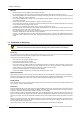
12. Advanced Settings B 0.7V Black level Image 12-1 G B R ∆G ∆R ∆Β Black level Image 12-2 One can conclude here that a good color tracking can only be met by using three previously (input) balanced color signals Analog Digital Conversion The analog color signals must pass through an Analog/Digital conversion circuit prior to any digital processing in the PMP. A typical ADC transforms the analog value into an 8 bit coded digital signal.
12. Advanced Settings 12.4.2 Adjusting the input balance How can it be done ? To balance the three color signals of a particular source there are conditions; in fact we must know the black and the white level of the source i.e. : 1. The source in question must be able to generate a white signal, ideally a 100% white (background) full screen pattern 2.
12. Advanced Settings A slider bar appears. Adjust with the ↑ or ↓ until there is no blue noise visible in the black areas. Advanced Settings Gamma Color Temperature Input Balance Noise Reduction Film mode detection [ON] Video AGC Display Settings Installation Service Input Balance Black Balance Black balance White balance Black balance red Black balance blue Back Back Back Menu 12-8 Menu 12-9 Menu 12-10 White balance 1. Select Advanced Settings. 2. Press ENTER to activate.
12. Advanced Settings When Automatic is selected, the Adjust option is grayed out. Advanced Settings Noise Reduction Gamma Color Temperature Input Balance Noise Reduction Film mode detection [ON] Video AGC Display Settings Installation Service Adjust [Manually] Back Back Menu 12-14 Menu 12-15 Adjusting the noise reduction manually. 1. Check first if the noise reduction is set to manually. If yes, go to step 2 If no, Select first automatic and press ENTER to toggle to manually. 2. Select Adjust.
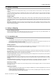
12. Advanced Settings [on] : film mode detection is enabled. [off] : film mode detection is disabled. Advanced Settings Gamma Color Temperature Input Balance Noise Reduction Film mode detection [ON] Video AGC Display Settings Installation Service Back Menu 12-16 12.7 Video Gain About Video Gain The automatic gain control for video and S-Video sources can be switched off. Then it is possible to adjust the gain manually. When a YUV video signal, no AGC is available but the video gain can be adjusted.
12. Advanced Settings 12.8.1 Rotate Rotate is only available when the optional rotator module is inserted in the Solaris LC40. About rotate With the rotate function it is possible to go from a normal landscape image to a portrait image. Image 12-6 Display rotation A B Landscape Portrait, with same input image If you do not change anything to the viewport, the image will be compressed and stretched until it fills the display. How to activate a rotation 1. Select Advanced Settings. 2.
12. Advanced Settings How to change the backlight ? 1. Select Advanced Settings. 2. Press ENTER to activate. The Advanced Settings menu will be displayed. (menu 12-21) 3. Select Display Settings. 4. Press ENTER to activate. The Display settings menu will be displayed. (menu 12-22) 5. Select Backlight. 6. Press ENTER to activate. A slider bar will be displayed with the actual backlight level filled out. 7. Use ↑ or ↓ to adjust the backlight level to desired level.
12. Advanced Settings Possible file manipulations The possible file manipulations are : • Load : installation of a file for a new source 12.9.1.2 Load file set up About load file With load file, a file containing source specific settings for that source, will be loaded. This load file can be done automatically by the system or manually by the user. When done automatically, the file which corresponds the best with the input source will be loaded. The priority will be given to a custom file.
12. Advanced Settings 8. If you want to load from a list of matching file, select List matching files. If you want to load from the all available files, select List all files. 9. Select the desired file and press ENTER. While scrolling through the files, the image will be online adapted.
12. Advanced Settings Or, turn the thumb wheel to change the first digit. Press the thumb wheel to enter the selected value and to jump to the next digit. Handle in the same way for the second digit. When no signal Standby : [off] Delay (min) : 5 Shutdown delay Enter new value 05 Back Menu 12-33 Menu 12-34 12.9.3 Language Selection What can be done ? The OSD language can be changed to one of the available languages. How to change the language 1. Select Advanced Settings. 2. Press ENTER to activate.
12. Advanced Settings 4. Press ENTER to activate. The Installation menu will be displayed. (menu 12-39) 5. Press ENTER to activate. The Tile setup menu will be displayed. (menu 12-40) 6. Select Tiled setup [yes] or [no]. 7. Press ENTER to toggle between [yes] or [no]. [yes] The display is configured for a tiled setup. [no] The display is configured as a stand alone display. When [yes] is selected, the complete set up can be finished.
12. Advanced Settings 6. Enter the column number in which the display (tile) is situated. Tiled setup Tiled setup Tiled setup : [yes] Complete setup has: Rows: 3 Columns: 3 This panel is: Row: 1 Colomn: 1 Tiled setup : [yes] Complete setup has: Rows: 3 Columns: 3 This panel is: Row: 1 Colomn: 1 Back Back Menu 12-43 Menu 12-44 1 2 3 1 2 Image 12-7 Practical example to set up the configuration. • Start with the first display and give it a IR address.
12. Advanced Settings How to display the identification screen ? 1. Press ENTER to activate the menu structure. 2. Select Advanced Settings and press ENTER to activate. The advanced settings menu will be displayed. (menu 12-45) 3. Select Service. 4. Press ENTER to select. The service menu will be displayed. (menu 12-46) 5. Select Identification. 6. Press ENTER to display the identification screen.
12. Advanced Settings 12.10.3.1RS232 address How to change the RS232 address ? 1. Press ENTER to activate the menu structure. 2. Select Advanced Settings and press ENTER to activate. The advanced settings menu will be displayed. (menu 12-51) 3. Select Service. 4. Press ENTER to select. The service menu will be displayed. (menu 12-52) 5. Select Serial communication. 6. Press ENTER. The serial communication menu opens. (menu 12-53) 7. Select RS232 address and press ENTER. The RS232 address change menu opens.
12. Advanced Settings Possible values: - 9600 - 19200 - 30400 - 57600 - 115200 - 230400 Advanced Settings Gamma Color Temperature Input Balance Noise Reduction Film mode detection [ON] Video AGC Display Settings Installation Service Service Identification IR address : 004 Serial communication IR locking Restore factory defaults Serial Communication RS232 address : 001 Baudrate : [57600] Back Back Back Menu 12-55 Menu 12-56 Menu 12-57 12.10.
12. Advanced Settings How to change ? 1. Press ENTER on the RCU or press the thumb wheel once. The main menu will be displayed. (menu 12-61) 2. Select Service and press ENTER or the thumb wheel. The service menu will be displayed. (menu 12-62) 3. Select IR locking and press ENTER. The IR locking menu will be displayed. (menu 12-63) 4. Select Enter key and press ENTER. The IR key window opens. (menu 12-64) The first digit will be highlighted. 5. To change the value : Use ↑ or ↓ to change the value.
12.
A. Standard Source Set up Files A. STANDARD SOURCE SET UP FILES A.1 Table overview Table The following standard source files are pre-programmed in the display. 1. 2. 3. 4. 5. 6. 7.
A.
B. Optional Mounting Equipment B. OPTIONAL MOUNTING EQUIPMENT Overview • Wall Mounting Support • Table mounting support B.1 Wall Mounting Support B.1.1 Kit content Overview Image B-1 B.1.2 Horizontal Wall Mounting Support How to mount 1. Use the center cross (A) which indicates the middle of the Solaris LC40 to mark the drill holes (B) for the wall support. The diagonals of the Solaris LC40 must cross each other in the center of the center cross, see image B-5.
B.
B. Optional Mounting Equipment Image B-5 Final result B.1.3 Vertical Wall Mounting Support How to mount 1. Use the center cross (A) which indicates the middle of the Solaris LC40 to mark the drill holes (B) for the wall support. The diagonals of the Solaris LC40 must cross each other in the center of the center cross, see image B-9. image B-6) Note: Attention, always mount the bracket in the way that handle D on the left side. 2. Put the security handle (D) to the left. 3.
B.
B. Optional Mounting Equipment Image B-9 Final result B.2 Table mounting support How to use 1. Turn in a little bid four bolt on the backside of the Solaris LC40 (A). (image B-10) 2. Hook the panel into the mounting holes of the table mount support (A). (image B-11) 3. Slowly lower the panel until it rest on the support. 4. Secure by fixing the four bolts. 5. For easily cable connection, loosen wing nut B and turn the panel until it lays down. The cables can be connected in an easy way.
B.
C. Specifications C. SPECIFICATIONS C.1 Specifications Solaris LC40 Overview Technology TFT LCD Hor. viewing angle 170° Vert. viewing angle 170° Lifetime typical 50.000h Weight 25kg / 55.
C.
Glossary GLOSSARY 2:2 pull-down The process of transferring 24-frames/sec film format into video by repeating each frame (used for PAL DVD’s) as two video fields. ( AD ) 3:2 pull-down Method used to map the 24 fps of film onto the 30 fps (60 fields) or 25 fps (50 fields), so that one film frame occupies three video fields, the next two, etc. It means the two fields of every other video frame come from different film frames making operations such as rotoscoping impossible, and requiring care in editing.
Glossary 94 R5976672 SOLARIS LC40 13/01/2005
Index INDEX A Address 30 Program 30 RCU 30 setting 30 IR address 30 RS232 address 30 Advanced settings 63–65, 68–72, 74–75, 77–80 Color temperature 64 Display settings 70–71 Backlight 71 Rotate 71 Film mode detection 69 Gamma 63 Input balance 65 Installation 72, 74–75 File services 72 Language 75 Tiled setup 75 When no signal 74 Menu overview 63 Noise reduction 68 Service 77–80 Baudrate 79 Identification screen 77 IR address 78 IR locking 80 RS232 address 79 Serial communication 78 Video Gain 70 Aspect rat
Index S When no signal 74 Installation Guidelines 11 Configurations 11 General 11 IR address 30 IR locking 32 L Language setup 75 LCD panel 30, 32 Controlling 30 IR locking 32 Loop through connection RGB output 24 24 M Menu structure 35–36 Slider box 36 Start up 35 Use 35 Mounting equipment 85, 87, 89 Table mounting support 89 Wall mounting support 85, 87 Horizontal 85 Vertical 87 N Noise reduction 68 P Packaging 7 Box content 7 Way of 7 Phase 49 PIN code 80 Change 80 PiP 32, 55–58 Function keys 32
Revision Sheet To: Barco nv Events/Documentation Noordlaan 5, B-8520 Kuurne Phone: +32 56.36.89.70, Fax: +32 56.36.88.24 E-mail: antoon.dejaegher@barco.com, Web: www.barco.