MD-4221 42” HD MEDICAL LCD MONITOR User manual
Copyright notice This document is copyrighted. All rights are reserved. Nor this document, nor any part of it, may be reproduced or copied in any form or by any means - graphical, electronic, or mechanical including photocopying, taping or information storage and retrieval systems without written permission of Barco © 2008 Barco N.V. All rights reserved.
Table of Contents Table of Contents ....................................................................................... 4 Preface........................................................................................................ 5 Important notice.................................................................................... 5 Environmental information................................................................... 5 Safety Instructions ......................................................
Preface Important notice Notice Although every attempt has been made to achieve technical accuracy in this document, we assume no responsibility for errors that may be found. Our goal is to provide you with the most accurate and usable documentation possible; if you discover errors, please let us know. Barco software products are the property of Barco. They are distributed under copyright by Barco N.V., for use only under the specific terms of a software license agreement between Barco N.V.
Safety Instructions On Safety 1. Before connecting the AC power cord to the DC adapter outlet make sure the voltage designation of the DC adapter corresponds to the local electrical supply. 2. Never insert anything metallic into the cabinet openings of the Liquid Crystal Display (LCD) monitor. Doing so may create the danger of electric shock. 3. To reduce the risk of electric shock, do not remove cover. No user-serviceable parts inside.
Warning When necessary, carry this product with at least 2 persons, using both handles on left and right side of the product. If you want the product to be installed on another place, please contact Barco Customer Service center. On installation 1. Openings in the LCD monitor cabinet are provided for ventilation. To prevent overheating, these openings should not be blocked or covered. If you put the LCD monitor in a bookcase or some other enclosed space, be sure to provide adequate ventilation. 2.
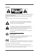
Caution To prevent fire or shock hazards, do not expose this unit to rain or moisture. Also, do not use this unit's polarized plug with an extension cord receptacle or other outlets unless the prongs can be fully inserted. The display is designed to meet the medical safety requirements for patient vicinity device. This device may not be used in connection with life support equipment. This symbol alerts the user that important literature concerning the operation of this unit has been included.
Use the proper power cord with correct attachment plug type. If the power source is 120V AC, use a power cord which is a Hospital Grade Power Cord with NEMA 5-15 style plug, labeled for 125 volts AC with UL and C-UL approvals. If the power source is a 240 V AC supply, use the tandem (T blade) type attachment plug with ground conductor power cord that meets the respective European country's safety regulations.
Servicing Do not attempt to service the apparatus yourself as opening or removing covers may expose you to dangerous voltages or other hazards, and will void the warranty. Refer all servicing to qualified service personnel. Unplug the apparatus from its power source and refer servicing to qualified personnel under the following conditions: • If the power cord or plug is damaged or frayed. • If liquid has been spilled into the apparatus. • If objects have fallen into the apparatus.
FCC Information This equipment has been tested and found to comply with the limits of a Class B digital device, pursuant to Part 15 of the FCC Rules. These limits are designed to provide reasonable protection against interference. This monitor can radiate radio frequency energy and, if not installed and used in accordance with the instructions, it may interfere with other radio communications equipment. There is no guarantee that interference will not occur in a particular installation.
RF Emissions CISPR 11 Class B Harmonic emissions IEC 61000-3-2 D Voltage fluctuations IEC 61000-3-3 Complies including domestic establishments and those directly connected to the public low-voltage power supply network that supplies buildings used for domestic purposes 2. Guidance and manufacturer's declaration - electromagnetic immunity The MD-4221 is intended for use in the electromagnetic environment specified below.
Electromagnetic compatibility Warning When this device is connected with other electrical equipment, leakage currents may be additive. To minimize total leakage current per patient, ensure that all systems are installed according to the requirements of IEC 60601-1-1. Caution Portable and mobile RF communications equipment may affect the normal function of the display.
Recommendations for using your display system 1. Optimize the lifetime of your display Enabling the Display Power Management System (DPMS) of your display (in the display’s Settings menu) will optimize LCD backlight lifetime by automatically switching off the backlight when the display is not used for a specified period of time. By default, DPMS is enabled on your display, but it also needs to be activated on your workstation. To do this, go to “Power Options Properties” in the “Control Panel”.
• Do not apply pressure to the screen or touch the screen with bare fingers or objects. Pressure can affect image quality. Cosmetics and oils on the skin are both detrimental to the screen and difficult to remove. • Allow the display to warm up to room temperature before turning it on. Avoid sudden temperature changes in the environment, as this may cause condensation, which damages the display. • Do not set up the display near strong light or heat sources.
Serial Number. Top-Bottom. Fragile. Do not get wet. Maximum Stacking. Indicates proof of conformity to applicable European Economic Community Council directives and to harmonized standards published in the official journal of the European Communities. Medical Equipment is in accordance with UL 60601-1 and CAN/CSA C22.2 No.601.1 in regards to electric shock, fire hazards, and mechanical hazards. Tested to comply with FCC Class B standards.
Introduction Quick Startup 1. Connect the power supply to the display via the power plug. 2. Plug into the AC inlet with power cord cable. 3. Connect the video source to this monitor. 4. Apply power to the peripheral device. 5. Turn on the switch of this monitor.
Connectors 18
Mechanical product drawing 20
Controls Remote control Key F1 Description Input Selection, same as input button on user controls F2 PiP Button on OSD F3 PiP Swap F4 No Function F5 Shows RS232 address UP Move in OSD same as up key on user controls DOWN LEFT RIGHT Move in OSD same as down key on user controls Adjust in OSD, same as - key Adjust and enter adjust in OSD, same as + key ADJ Enter OSD, same as menu button on user controls EXIT Exits OSD, same as menu button on user controls ENTER Standby PAUSE || TEXT ? Enter
OSD buttons position OSD Button Function An 8-button keypad, located on the right hand side of the display, allows the user to make adjustments to various display parameters using the On Screen Display (OSD) system.
● Power LED Green : Normal mode Amber: Standby mode Amber: Soft power-off ● On-Screen Display (OSD) Function Button 1. POWER : Turns ON/OFF the monitor. 2. MENU : With OSD deactivated, Activate the OSD menu. With OSD activated, Exit from main menu or sub menu. 3. PIP : With OSD deactivated, Hot key of PIP mode. 4. UP : With OSD deactivated, Hot key of the brightness control and increases the brightness. With OSD activated, move the cursor upward. 5.
On-Screen Display Menus Adjust 24
BRIGHTNESS Increase or decrease the brightness. (Range : 0~100) CONTRAST Increase or decrease the Contrast. (Range : 0~100) SHARPNESS (1) Adjusts the sharpness of video image. (Range : 0~100) SHARPNESS (2) Adjusts the sharpness of video image. (SOFTEST, SOFT, NORMAL, SHARP, SHARPEST) COLOR (3) Changes the color value. (Range : 0~100) HUE (3) Changes the Hue. (Range : 0~100) BACKLIGHT Adjusts backlight dimming level. (Range : 0~100) PHASE (4) Adjust backlight dimming level.
Advanced SCALING Change the image size (Best Fit, Fit Width, Fit Height,Native,Full Display) H POSITION (6) Adjust the horizontal position of the displayed source image.(Range : 0~100) V POSITION (6) Adjust the vertical position of the displayed source image. (Range : 0~100) POWER SAVE On/Off the power save function DISPLAY FUNCTION Adjust GAMMA value. (NATIVE,GAMMA1.8,GAMMA2.0,GAMMA2.2,GAMMA2.4, GAMMA2.6,DICOM,VIDEO) OVER SCAN Adjust the displayed size.
Setup LANGUAGE Change the OSD language. (8 languages) BACKGROUND Set the Background color RS-232 BAUDRATE Change RS232 BAUDRATE (115200,38400,19200,9600) RS-232 ADDRESS Set the RS232 Address.(Range : 1~255) OSD COLOR Adjust the OSD background from white opaque to half translucent. OSD POSITION Change the OSD position OSD TIMEOUT Adjust time until the OSD Menu will disappear after adjusting the menu.
PIP LAYOUT Change the OSD layout. (Single, PIP, PBP1, PBP2) SOURCE 1 Change the primary source. SOURCE 2 Change the secondary source. SIZE Adjust PIP size. (Small,Large) POSITION Change the PIP position. (9 positions) TOGGLE Swaps the position of the Primary and Secondary images.
OSD functions description Menus Function Descriptions BRIGHTNESS Setting the brightness too high or too low will decrease the amount of visible information. CONTRAST Setting the Contrast too high or too low will cause loss of some grayscales. FREQUENCY Do not adjust freely. It will adjust fine state automatically after auto adjustment. When frequency value is wrong, the image has the wrong horizontal size or contains noise. PHASE Do not adjust freely.
Standard signal table PC modes supported Horizontal Frequency (KHz) Vertical Frequency (Hz) Clock Frequency (MHz) 640 X 350 @70Hz 31.469 70.087 25.175 720 X 400 @70Hz 31.469 70.082 28.324 640 X 480 @60Hz 31.469 59.940 25.175 640 X 480 @75Hz 37.500 75.000 31.500 800 X 600 @60Hz 37.879 60.317 40.000 800 X 600 @75Hz 46.875 75.000 49.500 1024 X 768 @60Hz 48.363 60.004 65.000 1024 X 768 @75Hz 60.023 75.029 78.750 1152 X 864 @60Hz 54.348 60.053 80.000 1152 X 864 @75Hz 67.
SDI video format Output Signal Description SMPTE-274M 1080i (60 / 59.94 / 50) 1080p (30 /29.97 / 25 / 24 / 24sF / 23.98 / 23.98sF) SMPTE-296M 720p (60 / 59.94 / 50) SMPTE-260M 1035i (60 / 59.94) SMPTE-125M 480i (59.94) ITU-R BT.
Signal connector pin assignments VGA (15-pin D-sub) Pin No. Assignment Pin No. Assignment 1 Red 9 No Connection 2 Green 10 Ground-Sync 3 Blue 11 Ground 4 Ground 12 DDC Data 5 DDC 5V Standby 13 H.Sync Cable Connection check 14 V.Sync 6 Ground-Red 15 DDC Clock 7 Ground-Green 8 Ground-Blue DVI in-out (24-pin DVI-D) Pin No. Assignment Pin No. Assignment 1 T.M.D.S. Data2- 13 No Connection 2 T.M.D.S. Data2+ 14 +5V Power 3 T.M.D.S.
7 DDC Data 19 T.M.D.S. Data0 Shield 8 No Connection 20 No Connection 9 T.M.D.S. Data1- 21 No Connection 10 T.M.D.S. Data1+ 22 T.M.D.S. Clock Shield 11 T.M.D.S. Data1 Shield 23 T.M.D.S. Clock+ 12 No Connection 24 T.M.D.S. Clock- C-video (BNC) Pin No. Assignment 1 Composite 2 Ground S-Video (BNC) Pin No.
RS232C (D-Sub 9-pin) Pin No. Assignment 1 No Connection 2 TXD 3 RXD 4 No Connection 5 Ground 6 No Connection 7 No Connection 8 No Connection 9 No Connection SDI (BNC) Pin No.
RGB HV/RGBS/YPbPr (BNC) Pin No.
Specifications Model MD-4221 Type TFT-LCD Screen Size 42 inch Maximum Resolution 1920 X 1080 @ 60Hz Pixel pitch 0.4845(H) mm X 0.4845(V) mm Display Colors 16.
BARCO MID GENERAL WARRANTY TERMS AND CONDITIONS Applicable from Jan 1st 2008 ARTICLE 1: PRODUCT WARRANTY Barco nv, Medical Imaging Division warrants that the equipment will be free of defects in workmanship or material for the warranty period or the specific period of a warranty extension program.
an authorised service centre). 1.4 Replacement parts used shall be new or equivalent to new parts for the revision level of the equipment. A replacement LCD panel will be new or similar run time. The warranty period for the replacement parts will expire at the same moment as the original warranty period of the equipment. All parts replaced hereunder and returned to Barco nv, MID (or an authorised service centre) shall become the property of Barco nv, MID (or the authorised service centre). 1.
Normal wear and tear, use under circumstances exceeding specifications, such as use in dusty environment or under excessive temperature conditions, abuse, unauthorised repair or alternation, lack of proper configuration or maintenance, damaged or modified or removed serial number, cosmetic refurbishment. 2.5 Repair or replacement of consumables1 or specific parts that by definition are subject to wear and tear, including but not limited to: a. CRT’s, LCD panels b.
v. LCD luminance uniformity that is in within the product specifications or luminance uniformity performance that is inherent to LCD technology. Barco nv, MID does not warrant a minimum life time nor a performance of any of the consumables. 2.6 Replacement of moveable parts such as power cords, remote controls, … 2.
ARTICLE 5: DISCLAIMER OF WARRANTIES BARCO NV, MID DISCLAIMS ALL WARRANTIES, EXPRESSED OR IMPLIED, INCLUDING ALL IMPLIED WARRANTIES OF MERCHANTABILITY AND FITNESS FOR A PARTICULAR PURPOSE.
B410615-01 August 2009 Barco N.V. President Kennedypark 35 B-8500 Kortrijk, Belgium visit us at the web: www.barco.com Support helpdesk: Asia Pacific: +886-2-8221-6868 ext.