Nio Fusion 4MP Online User Guide
(This page intentionally left blank.
Using the online User Guide Using the online User Guide Sources of information Overview of product documentation Document Content Quick install sheet (poster in box) Gives a short overview of the installation of a complete system. Getting started guide (booklet in box) Gives a detailed description of the installation and connection of a complete system.
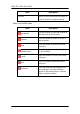
Using the online User Guide Item Favorites Description Allows to add and remove help topics to a list of favorites. (requires cookies) Items in the toolbar frame Item Synchronize Press this button to show the location of the help item in the Contents. Previous Press this button to move to the previous help topic. Next Press this button to move to the next help topic. Related topics Press this button to display related topics (if available).
Graphic board control panel Graphic board control panel This chapter describes how to configure the displays in your BARCO NIO FUSION 4MP Display System using the tools available through the Advanced button on the Settings tab of the Windows Display Control Panel. Note: If you purchased Barco Medical Displays only and not a complete BARCO NIO FUSION 4MP Display System you will need to refer to the user manual for the display controller you are using.
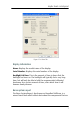
Graphic board control panel Barco Driver Properties Accessing the Barco tab Note: You must have logged on to Windows using an account with administrator privileges in order to use the Barco portions of the Windows Display Control Panel to change any display settings. 1. Open the Windows Display Control Panel by one of the methods below: a) Start > Settings > Control Panel > Display b) Open the “Display Properties Control Panel” by right clicking in an empty area on the desktop, then select Properties.
Graphic board control panel Figure 1: Ex: Barco Tab Display Information Name: Displays the model name of the display. Serial Number: Displays the serial number of the display. Backlight LifeTime: This is the amount of time in hours that the backlight has been on. The backlight will typically last a very long time, but will only be able to hold the recommended calibrated luminance for a certain amount of time, after which time it will become slowly dimmer.
Graphic board control panel installed in your system. This information is used by the Barco MIS Support team when trying to resolve customer issues. MediCal QAWeb Clicking on the QA Web button will launch the MediCal QAWeb application. Please refer to the MediCal QAWeb manual for information about this application.
Graphic board control panel • Clone The primary display is cloned to the secondary display. Color Format • 24-Bit TrueColor Mode • 30-Bit TrueColor Mode (HDR) Display Resolution • Sets display resolution for 1 or 2 displays. Note: To switch out of SingleView or Clone mode, the buttons in this Control Panel page must be used. The main Windows Control Panel cannot be used. Depending on your system, certain configurations can be disabled.
Graphic board control panel OpenGL and Direct3D The OpenGL and Direct3D pages of the Advanced Properties page are divided into two sections: Main Settings and Custom Settings. Main Settings In the Main Settings section there is a slider bar which allows the user to adjust the OpenGL or Direct3D settings for optimum performance, optimum quality or for a point in between. There is also a checkbox provided for enabling Custom Settings.
Graphic board control panel Please refer to the on-line help (click on the “?” in the control panel’s openGL tab) for more information on using advanced features such as Anisotropic Filtering. SMOOTHVISION The Advanced Settings tab enables you to apply ATI’s SMOOTHVISION technology for full-scene anti-aliasing. SMOOTHVISION improves image quality by removing jagged edges (anti-aliasing) from 3D images, resulting in smoother, more natural looking objects.
Graphic board control panel OpenGL Profiles The Configuration page enables you to customize display profiles for individual applications. Typically, you would change these settings for one or more of the following reasons: • Diagnostic purposes. • Fine-tuning a specific application/system configuration. • Specific settings recommended by your hardware or software documentation. • Tuning your application/system environment for best performance and memory usage.
Graphic board control panel configuration controls on this tabbed dialog to obtain the desired display parameters for the selected application. To remove the selected configuration profile completely, select the name of the application from the Configuration Profiles list box and click Delete. Note: You cannot delete the factory-set configuration profiles. Click the Apply or OK button to enable your Configuration settings.
Graphic board control panel palette mode supports 32 bit True Color, Barco recommends that when using a using a color display in conjunction with your highresolution grayscale display(s) that you still set the color display as the primary monitor of the Windows desktop.
Display information Display information Precautions 1. Optimize the lifetime of your display Enabling the Display Power Management System (DPMS) of your display (in the display’s Settings menu) will optimize its diagnostic lifetime by automatically switching off the backlight when the display is not used for a specified period of time. By default, DPMS is enabled on your display, but it also needs to be activated on your workstation. To do this, go to “Power Options Properties” in the “Control Panel”.
Display information diagnostic performance of the product. To ensure optimal product quality, Barco applies strict selection criteria for its LCD panels. To learn more about LCD technology and missing pixels, consult the dedicated white paper available at www.barcomedical.com. 4. Enhance user comfort Every Barco multi-head display system is color matched with the highest specification in the market. Barco recommends keeping color-matched displays together.
Display information Display controls Overview of controls The front controls are soft touch keys. When you touch any of them while no on-screen display (OSD) is on the screen, the front illumination is switched on for a few seconds. When you touch a key again while the illumination is on, the function of the key is executed. 1 2 3 4 5 Figure 2: Front view 1. Left/Down touch key To move down or decrease values in the OSD. 2. Right/Up touch key To move up or increase values in the OSD. 3.
Display information To display the OSD (on-screen display). In the OSD, this button acts as Enter button to make selections. 4. Standby touch key To put the display in standby mode. 5. Power LED Indicates the display’s power status. Green: Display is on (when enabled in the OSD). Orange: Display is in Standby power-saving mode. Off: Display is disconnected from the power or the LED’s on state is disabled in the OSD.
Display information into edit mode. This is indicated by the scroll bar becoming longer. SETTINGS DPMS Power LED User Controls EXIT On On On Figure 3: Setting is selected SETTINGS DPMS Power LED User Controls EXIT On On On Figure 4: Edit mode is active Use Up or Down to change the value. Use Enter confirm the change. to Changes are saved automatically after confirming. 6. Some items in the menus cannot be changed. They are readonly values, displayed in light gray.
Display information 2. A warning message appears. Press the Stand-by touch key again to switch the display into stand-by or press any other key to keep the display in on state. To switch from stand-by to on state: 1. Touch any of the soft touch keys. The front illumination is switched on for about 10 seconds. 2. While the illumination is switched on, touch the Stand-by touch key to switch the display on.
Display information display with office applications such as word processing. You can switch between both modes by touching the up and down keys at the same time. On-screen display (OSD) Complete OSD Luminance and color menu Name Description Measured luminance Indicates the actual luminance measured by the internal sensor. This is a read-only value. It is expressed in a percentage of the calibrated value (100% is calibrated). Luminance target Allows to manually adjust the luminance target.
Display information Display Function menu Name Description Display function Allows to select from a list of predefined display functions. If the DICOM DF is selected, a number of additional settings is available. ALC & DICOM options Jumps to the ALC & DICOM Options submenu, which allows to edit the settings for the DICOM display function. This function is available only when the DICOM DF is selected.
Display information Name Description Reading room def. Jumps to the reading room definition submenu, which allows to edit the reading room condition settings. Calibration info Jumps to the calculation information submenu, which displays information about the values taken into account to recalculate the DICOM DF. Reading room definition submenu Name Description Reading room Indicates the reading room type you are editing. You can select another room to edit by using the Up or Down touch keys. Max.
Display information Name Description Bright luminance Shows the bright luminance value taken into account to calculate the DICOM DF. Dark luminance Shows the dark luminance value taken into account to calculate the DICOM DF. Ambient correction Shows the ambient light correction value taken into account to calculate the DICOM DF, expressed in cd/m². Settings menu Name 24 Description DPMS Allows to switch the display power management system on/off. See note below.
Display information Name Description Input Switch Mode Select “Auto” if you wish the display to select the video inputs automatically. If only one video input is connected, the image will be shown in the center of the screen. If both video inputs are connected, the video signal connected to the “Left” input is shown on the left side of the screen and the signal connected to the “Right” connector is shown on the right side.
Display information Information menu Information Name Description Product The display type Serial No Indicates the display serial number SW Number Displays the internal software number SW Version Displays the current internal software version Display Lifetime Indicates the total time the display has been operating, including the time in stand-by Backlight Lifetime Indicates the total time the display has been operating, excluding the time in stand-by Changing Display Functions Concepts • The
Display information Maximum Ambient Light defines the maximum light allowed in this type of room. This value can be adjusted within certain limits determined by the selected reading room. Preset Correction Value is the predefined correction value for this reading room. This value can be adjusted within certain limits determined by the selected reading room. • The reading room parameters are pre-defined in the display according to the AAPM (American Association of Physicists in Medicine).
Display information You can select the following DFs: Name Description DICOM Select a DICOM display function for most medical viewing applications. The DICOM function results in more visible grayscales in the images. Dyn Gamma 2.2 Dyn Gamma 1.8 These are gamma functions that are shifted to take into account the non-zero luminance of an LCD panel when driven with a “black” signal. They are especially useful in CT applications to improve the perception of low Haunsfield values.
Display information 2. In the ALC & DICOM Options menu, use Up or Down to to go into edit mode. select DICOM Offset. Use Enter 3. Use Up or Down to select an offset. to save the changes. 4. Use Enter You can select the following offsets: Value Description Dark Room The DICOM DF will be recalculated taking an ambient light value of 0 lux into account. This means that the measured ambient light does not influence the DICOM DF.
Display information You can select the following reading room types:: Name Description CR/DR/MAMMO Corresponds to light conditions in diagnostic reading rooms for computed radiology, digital radiology or mammography. This setting has the lowest maximum ambient light. CT/MR/NM Corresponds to light conditions in diagnostic reading rooms for computed tomography, magnetic resonance or nuclear medicine scans. Office Corresponds to light conditions in office rooms.
Display information go into edit mode. Use Up or Down to select the reading to confirm the selection. room. Use Enter 4. To modify the maximum ambient light for this reading room, use Up or Down to select Max. Ambient Light. Use Enter to go into edit mode. Use Up or Down to change the to save the changes. value. Use Enter You can change this value within certain limits determined by the selected reading room. 5.
Display information Switching Power LED on/off To switch the power LED on/off: 1. Touch any of the soft touch keys. The front illumination is switched on. 2. While the illumination is on, touch the Enter display the main menu. touch key to 3. Use the Up or Down touch keys to select the Settings to open the menu. menu. Use Enter 4. Use Up or Down into edit mode. to select Power LED. Use Enter 5. Use Up to select On or Off. 6. Use Enter or Down to go to save the changes.
Display information 6. Exit the OSD Now the user cannot display the OSD again until the user controls keycode is entered (see below). To enable the user controls again: 1. To enter the user controls keycode, the OSD must not be visible. 2. Touch any of the soft touch keys to switch on the front illumination. 3. While the illumination is on, touch the following keys in successive order: Enter , Down , Up , Down , Enter . As a result, the User Controls setting in the Settings menu is switched on again.
Barco web sites Barco web sites Visit Barco at: http://www.barco.com Visit Medical Imaging at: http://www.barco.
K5902003-01 November 2009 Barco nv Medical Imaging President Kennedypark 35 B-8500 Kortrijk, Belgium www.barco.