BARCO nv Communication Systems Th. Sevenslaan 106 B-8500 Kortrijk (Belgium) Tel.: +32.56.233.211 Fax: +32.56.233.461 E-mail: support.bcs@barco.com Website: http://www.barco.
PULSAR BG Contents CONTENTS 1 GENERAL DESCRIPTION................................................................................................................ 1-1 2 SPECIFICATIONS.............................................................................................................................. 2-1 INTERNAL LAYOUT ................................................................................................................................ 3-1 4 INSTALLATION.............................
Contents PULSAR BG 6.2 LAYOUT......................................................................................................................................... 6-4 6.2.1 Installation Of A VHF Or An Agile Filter Module .................................................................. 6-4 Installation Of An UHF Filter Module................................................................................................... 6-5 6.3 SETTINGS .............................................................
PULSAR BG General Description 1 GENERAL DESCRIPTION PULSAR: THE ULTIMATE MODULATOR The PULSAR is a TV modulator used to convert baseband audio and video signals into RF output signals ready to go into your cable network. Barco’s PULSAR is one of the first intelligent TV modulators in the world. Thanks to its built-in intelligence, all of the parameters important in a modulator, such as RF levels, modulation depth, audio deviation etc., can be remote controlled.
PULSAR BG Specifications 2 SPECIFICATIONS All specifications are measured with the RF output terminated with a passive load of 75 Ohm. 2.1 General Specifications • • • • • • Ambient temperature range Within specs Operation Storage Power supply Power supply -48 V Input voltage range Type Filter input Fuse Max.
Specifications PULSAR BG 2.3 RF output • • • • Connector Output impedance Return loss Frequency • Output level • • C/N ratio ( 5 MHz BW) Amplitude response • • • • • Slope control Slope calibration Phase noise Harmonics and spurious radiation Sound / Vision ratio BNC 75 Ohm ≥ 15 dB between Fv - 1 MHz and Fv + 5.5 MHz; ref.
PULSAR BG Specifications IRT two carrier stereo • • • • • IF sound carriers Preemphasis Frequency response Distortion S/N ratio • Crosstalk 33.4 MHz and 33.158 MHz 50 µs 30 Hz - 15 kHz; tolerance : ± 0.5 dB; ref. = 100 Hz 30 Hz - 15 kHz at ± 30 kHz deviation: < 0.5% ≥ 62 dB (Quasi Peak Detector) at ± 30 kHz deviation @ 1 kHz audio signal; Video : sync only Dual sound at 1 kHz:> 60 dB Stereo at 1 kHz : > 36 dB 2.7 Video modulation spec.
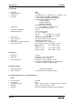
PULSAR BG Internal Layout 3 INTERNAL LAYOUT STATUS & CONTROL AUDIO SUBC MAIN VIDEO AUDIO INPUTS FUSE MAIN AUX VIDEO RS 485 AUX IN OUT REF OUT IN IF CW IN OUT VIS IF IN SND IF AUX IF IN OUT REF VID VID OUT AUX CIF IN COMP IF RF OUT J54 8 J45 J11 CIF IN MAIN BOARD UP CONVERTER 12 14 13 9 POWER SUPPLY 10 RF OUT U69 J22 CHANNEL FILTER RF AMPLIFIER > J16 14 PULSAR J17 U65 J18 J10 J21 J24 J19 J32 U7 15 TV Modulator ENTER INPUT ESC SETTINGS MODULATION RF
PULSAR BG Installation 4 INSTALLATION 4.1 RACK MOUNTING When mounting the PULSAR units, use 19 inch racks, preferably those with a depth of at least 70 cm. The units should be mounted adequately, so as to secure optimal operation and reliability of your unit. Use sliders compatible with the 19 inch racks used to support the PULSAR properly. When mounting more than one unit, we advise you to leave a space of at least one unit in between. These spaces can be covered afterwards with ventilation profiles.
Installation PULSAR BG 4.2.1 Power Supply 230 VAC The fuse is a 0.5 AT (slow blow) fuse, ordernumber C314115. Use 250 V type fuses only. 4.2.2 Power Supply -48 VDC The PULSAR can be equipped with a -48 VDC power supply, typically demanded in telecom environments. The -48 VDC power supply connector can be a D-type or a ComBiCon type connector. Look at the following sections for a detailed information about the wiring.
PULSAR BG Installation 4.3 INPUT & OUTPUT CONNECTORS MAIN VIDEO Baseband video signal input for the main program. BNC type connector (Loop through in option) VIS IF (Optional) Vision IF loop input & output. This IF loop can be used in combination with IF loop scramblers. F type connectors SND IF (Optional) Sound IF loop input & output. This IF loop can be used in combination with IF loop scramblers. F type connectors COMP IF Composite IF loop input & output.
Installation IF CW OUT (Optional) When the PULSAR is equipped with the reference carrier output option or vision reference carrier output the signal will be available on this connector BNC type connector AUX IF IN (Optional) When the option composite IF auxiliary input is installed this is the input connector for the IF signal. BNC type connector REF VID IN (Optional) The reference input is used when the option main scrambled aux unscrambled is installed in combination with a two carrier stereo system.
PULSAR BG Installation 4.3.1 RS-485 Remote Control The RS-485 Remote Control connector is a 9-pins SubD male connector. All important modulator parameters such as RF level, modulation depth, audio deviation and all possible functional selections can be remotely controlled from a PC with BARCO’S ROSA software and/or the client-server ROSA/COPERNICUS system. This makes it possible to use the PULSAR in applications such as digital to analog nodes in super trunk systems and headends in rural or remote areas.
Installation PULSAR BG 4.3.2.2 Status & Control The lower row of the screw terminal is used as a status & control connector. Via these hard contacts (TTL level) it is possible to control certain parameters of the modulator.
PULSAR BG Installation 4.4 INSTALLING THE PULSAR 4.4.1 Rear Panel Of The PULSAR COMPOSITE IF LOOP AUDIO INPUTS RF OUTPUT VIDEO IN POWER CORD FUSE RS 485 AUDIO INPUTS STATUS & CONTROL VIS IF MAIN VIDEO AUDIO SUBC AUX VIDEO SND IF IN OUT MAIN AUX COMP IF IN OUT REF IF CW AUX IF IN OUT IN OUT RF OUT REF VID IN IN AUX CIF VID REF RS 485 4.4.
Installation PULSAR BG 4.4.3 Audio Connections The impedance and the balance of the input can be changed by means of jumpers on the mainboard. The factory setting is: balanced audio inputs with 600 Ohm impedance.
PULSAR BG Installation 4.5 REMOTE CONTROL 4.5.1 General The RS-485 Remote Control connector is a 9-pins SubD male connector. All important modulator parameters such as RF level, modulation depth, audio deviation and all possible functional selections can be remotely controlled from a PC with BARCO’S ROSA software and/or the client-server ROSA/COPERNICUS system.
Installation PULSAR BG 4.5.2 Communication Example And Installation For ROSA A communication example is shown in the figure below. The communication between the headend and the dispatching center in this example is established via a modem. The telephone network (PSTN) is used to communicate with the PC’s. The COMMBOX (Communication Organizer) in the headend is used to connect all the PULSAR modulators with the ROSA system.
PULSAR Operation 5 OPERATION 5.1 FRONT PANEL DESCRIPTION Front Panel Display The settings of the active menu are displayed on the front panel display. PULSAR MOD : 90% 030/30 kHz Menu Push Buttons The menu push buttons are used to select and change settings. ENTER ESC USER Arrows: To scroll through the menus shown on the display. Enter: To confirm the setting. Esc: To quit the setting without saving. User: To select the setting saved in the user settings memory.
Operation Auto: PULSAR Only with the option Aud/Vid Aux input and Main scrambled/Aux unscrambled there is the possibility to switch automatically to the auxiliary input when Main video is lost. Modulation Selection Buttons The modulation selection buttons are used to change the modulation parameters. MODULATION VIDEO AUDIO Video: To change the video modulation depth of the vision carrier. Audio: To change the audio deviation of the sound carriers.
PULSAR Operation 5.2 USING THE MENU KEYS When starting up the unit or when the unit is in operation, the menus are locked: the LOCK button is lit up green and the display back-light is switched off.
Operation PULSAR 5.3 SYSTEM CONFIGURATIONS 5.3.
PULSAR Operation 5.3.2 Setting Up Communication Make following settings in the config menu to enable the PULSAR to send and receive data to and from the COPERNICUS ELEMENT MANAGER. 1. COMMPORT MESSAGES: Enabled 2. COMMPORT ADDRES: Range: 01h to 7Eh Each PULSAR must have an unique commport address. Do not use address 00h, because if another PULSAR is reset with “Clear all data & restart”, it automatically gets address 00h too. Two devices with the same address will cause communication problems.
Operation PULSAR 5.3.3.6 View Hardware Configuration This submenu displays the hardware configuration of the unit. The table below gives an overview of all possible messages. PULSAR HARDWARE CONFIGURATION SECOND SOUND CARRIER MRS/YES In case of a two carrier stereo system STANDARD BG TV standard of the Pulsar VIDEO MOD 90% Video modulation depth AUDIO DEV 30 kHz Audio deviation of the sound carrier VIS CAR FREQ 38.9 MHz Frequency of the vision carrier SND CAR1 FREQ 33.
PULSAR Operation 5.3.4 Alarms And Errors If the STATUS key is blinking red, there are alarms or errors that are not acknowledged yet. If you press the STATUS key, the VIEW ALARMS menu appears. If an alarm condition is over, that alarm is removed from the list.
Operation PULSAR 5.4 SETTINGS SETTINGS FREQ LEVEL MODE Adjustable between 50 and 60 dBmV. RF OUTPUT LEVEL: 60 dBmV FREQUENCY: 600.000 MHz NAME: PULSAR agile Pulsar channelized Pulsar The channel name can be modified. (max 15 characters). MOD-METER: SYNC SYNC S/V RATIO: -10 dB Adjustable between -8 and -20 dB. -13 dB, -20 dB CHANNELIZED : 275.
PULSAR Operation 5.4.2 RF Output Level The RF output level can be set between 50 and 60 dBmV in steps of 0.5 dB. The factory setting is 60 dBmV. 5.4.3 S/V Ratio The S/V ratio can be changed between –8 and –20 dB. The factory setting is – 13 dB. In case of two sound carriers: the S1/V and S2/V ratio are displayed. The S1/V ratio can be changed between –11 and –23 dB and is default –13 dB. The level of S2/V is default –20 dB and changes proportional to the S1/V value i.e.
Operation • PULSAR CLAMPING The video clamper is used to hold the blanking level constant, regardless of the changes in the average picture level. Two different methods of clamping are selectable: back porch or sync tip clamping. Back porch clamping is used in most cases and is based upon the sample & hold principle. It is especially used when hum rejection is wanted.
PULSAR Operation 5.5 MODULATION MODULATION Indicates the measured modulation depth. VIDEO AUDIO Indicates the modulation depth reference value. MOD: VAGC=OFF _ _ _ _ _ _ _ _ _ _ _ _ _ _ _ _ _ 90% MOD: = 90% VAGC=WHT _ _ _ _ _ _ _ _ _ _ _ _ _ _ _ _ _ 90% MOD: = 90% VAGC=SYN _ _ _ _ _ _ _ _ _ _ _ _ _ _ _ _ _ 90% Indicates the measured frequency deviation. AUDIO DEV: _ _ _ _ _ _ _ _ _ _ _ _ _ _ _ _ _ 030kHz Indicates the frequency deviation reference value. In case of stereo sound.
Operation PULSAR 5.6 INPUT The basic version of the PULSAR only has a main video input. When unlocking the PULSAR, the MAIN button lights up and the default screen is displayed.
PULSAR Installation Filter Module 6 INSTALLATION FILTER MODULE INSTALLATION OF A CHANNEL FILTER OR AN AGILE FILTER INTO THE PULSAR 6.1 INSTALLATION See the layout diagram for the correct locations of the boards, connectors and screws 6.1.1 Opening The PULSAR: • • • • • Unplug the power cord to switch off the PULSAR. Unscrew the nine screws (Torx 10) holding the top cover. Pull the top cover backwards and remove it. Loosen the nine screws (Torx 10) holding the bottom cover. Remove the bottom cover. 6.
Installation Filter Module Page 6-2 PULSAR
PULSAR Installation Filter Module 6.1.5 Closing The PULSAR • • • • • Put the bottom cover back onto the chassis. Tighten the nine screws (Torx 10) while pressing the bottom cover down. Turn the PULSAR upright. Put the top cover onto the chassis. Tighten the nine screws (Torx 10) while pressing the top cover down.
Installation Filter Module PULSAR 6.2 LAYOUT 6.2.
PULSAR Installation Filter Module 6.2.
Installation Filter Module PULSAR 6.3 SETTINGS As soon as the PULSAR has been powered up, the new frequency programmed in the eprom of the filter module will be read. In the menu FREQ, the new frequency and name will be displayed for a channelized PULSAR. In case of an agile filter: the name and the frequency of the devices are displayed in separated items. The frequency can be changed in steps of 12.5 kHz by using the UP and DOWN arrow.
PULSAR Options 7 OPTIONS 1. AUDIO/VIDEO AUX INPUT (P001) 2. IRT STEREO CODER (P010) 3. MAIN SCRAMBLED/AUX UNSCRAMBLED SUBSTITUTION (P002) 4. NICAM INTERCARRIER INPUT(P005) 5. COMBINED SOUND & VISION IF AUXILIARY INPUT (CIF) (P009) 6. VIDEO LOOP THROUGH (P003) 7. IF VISION/IF SOUND LOOPS (P011) 8. REFERENCE CARRIER INPUT (P007) 9. SEPARATE IF OUTPUTS (P012) 10. VISION CARRIER REFERENCE INPUT(P008) 11. DATALINE DECODER (P018) 12. REFERENCE CARRIER OUTPUT (P021) 13. VISION CARRIER REFERENCE OUTPUT (P020) 14.
PULSAR Audio / Video Auxiliary Input OPTION: AUDIO/VIDEO AUX INPUT ORDER NUMBER: C9825506 1 DESCRIPTION The Audio / Video Auxiliary Input for automatic fall-back switching enables the switching between main and auxiliary baseband input signals. With the front panel on “AUTO” the circuit will check the presence of sync pulses in the main video signal. If these are not available the unit will switch -after a short selectable delay- to the auxiliary standby signal.
Audio/Video Auxiliary Input PULSAR 3.2 Installing The Audio/Video Aux Input Board: • Bridges to be set on the Mainboard: Bridge BR15 BR16 BR27 Function Enables / Disables the Audio/Video Auxiliary Input board Only when a Stereo Coder board is installed Enables / Disables the Audio/Video Auxiliary Input board Activates / De-activates Audio/Video Auxiliary Input option Position* non-default non-default remove * The default position is the marked position.
PULSAR Audio / Video Auxiliary Input 4 LAYOUT 4.
Audio/Video Auxiliary Input PULSAR 4.
PULSAR Audio / Video Auxiliary Input Page 5
Audio/Video Auxiliary Input PULSAR 5 SETTINGS • • • • • Connect video and audio signals to the MAIN and AUX inputs. The aux video input is standard loop through. If necessary use the 75 Ohm termination delivered with the accessory set. Select the MAIN input. Select MODE Scroll into the MODE settings with the LEFT or RIGHT arrow for the DEFINE MAIN INPUT command. Select the VID/Baseband AUD mode with the UP or DOWN arrow. Confirm by pressing ENTER.
PULSAR • • • • • Audio / Video Auxiliary Input Select CONFIG Scroll in the CONFIG menu with the LEFT or RIGHT arrow for the MAIN TO AUX DELAY. Change the value to the desired main to auxiliary input delay by the UP or DOWN arrow. The selectable delay time is 1 to 120 seconds. Confirm by pressing ENTER.
PULSAR Stereo Coder (IRT) OPTION: STEREO CODER (IRT) ORDER NUMBER: C9825509 1 DESCRIPTION A Mono PULSAR can be converted into analogue two carrier stereo modulator only by plugging in the IRT Stereo Coder board on the mainboard. The second sound carrier will be automatically activated and the appropriate menus will be added or changed. The customer needs to do a minimum of settings. 2 INSTALLATION Please read this chapter carefully before installing the option.
Stereo Coder (IRT) 2.3 Closing The PULSAR • • • • • • Put the bottom cover back onto the chassis. Tighten the nine screws (Torx 10) while pressing the bottom cover down. Turn the PULSAR upright. Put the top cover onto the chassis. Tighten the nine screws (Torx 10) while pressing the top cover down. Replug the power cord.
PULSAR Stereo Coder (IRT) 3 ALIGNMENT • • • Select FACTORY RECALL in the CONFIG menu, press the DOWN arrow and ENTER. P15 (on the mainboard) has been aligned for Mono, thus needs to be realigned. For the alignment: - Connect any kind of video (1 Vpp) to the input. - In the menu MODE, scroll to the item STEREO CODER and select DUAL SOUND. SETTINGS FREQ LEVEL MODE STEREO CODER: DUAL SOUND MONO+P STEREO MONO - In the AUDIO menu two bars are visible now.
Stereo Coder (IRT) PULSAR 4 LAYOUT STATUS & CONTROL AUDIO SUBC MAIN VIDEO AUDIO INPUTS FUSE MAIN AUX VIDEO RS 485 AUX IN OUT IF CW REF OUT IN VIS IF OUT IN SND IF IN IN REF VID AUX IF OUT OUT VID OUT IFs2 IN RF OUT COMP IF STEREO CODER CIF IN UP CONVERTER P15 BR13 POWER SUPPLY BR14 P4 MAIN BOARD RF OUT U69 CHANNEL FILTER RF AMPLIFIER U65 U7 > PULSAR TV Modulator ENTER INPUT ESC SETTINGS MODULATION SYSTEM RF TEST -20 dB USER Page 4 MAIN AUX AUTO VIDEO A
PULSAR Stereo Coder (IRT) 5 SETTINGS Automatically some menus will be adapted: • In the menu AUDIO, there are now two bars indicating the deviation for each sound carrier. Refer to the chapter 3: Alignment for more details.
PULSAR BG Main Scr/Aux Unscr OPTION: MAIN SCRAMBLED/AUX UNSCRAMBLED SUBSTITUTION ORDER NUMBER: C9825565 1 DESCRIPTION A PULSAR equipped with this option is able to work with specified (see warning) scrambled video on the main (scrambled) input. An unscrambled signal will be placed on the aux input. If the detector does not find any signal at the main input, the PULSAR will switch automatically -after a short selectable delay- to the unscrambled signal at the aux input.
Main Scr/Aux Unscr PULSAR BG CONNECTION DIAGRAM SCRAMBLER - PULSAR (1/2) Mainboard REF VIDEO Unscrambled Video J56 Sync Separator U57 BR23 Scrambled Video MAIN INPUT J61 J62 BR1 J53 75E AUX INPUT J54 DC Coupled Video processing board BR21 75E Scrambler Audio Selector Unscrambled Video Figure 1 : Connection Diagram Scrambler - Pulsar Mainboard REF VIDEO Unscrambled Video Scrambled Video J56 Sync Separator U57 BR23 MAIN INPUT J61 J62 BR1 J53 AUX INPUT J54 BR21 75E Scrambler
PULSAR BG Main Scr/Aux Unscr CONNECTION DIAGRAM SCRAMBLER - PULSAR (2/2) Unscrambled Video Mainboard REF VIDEO J56 Sync Separator U57 BR23 Scrambled Video MAIN INPUT J61 J62 BR1 J53 75E AUX INPUT J54 DC Coupled Video processing board BR21 Scrambler Audio Selector Unscrambled Video Figure 3 : Connection Diagram Scrambler - Pulsar With loop through on scrambler Unscrambled Video Mainboard REF VIDEO J56 Sync Separator U57 BR23 Scrambled Video MAIN INPUT J61 J62 BR1 J53 75E AUX INPU
Main Scr/Aux Unscr PULSAR BG 2 SPECIFICATIONS - Video/Audio specifications ...................................................... unchanged - DC-offset ................................................................................ ±0.5 V (adjustable) 3 INSTALLATION Please read this chapter carefully before installing the option. REMARK The installation procedure is only necessary when ordering this option separately.
PULSAR BG Main Scr/Aux Unscr 3.
Main Scr/Aux Unscr • PULSAR BG If the option Stereo Coder is installed following two items must be configured: Bridge BR1 Function Retrieve sync pulses of the scrambled input from VID REF Input / Mainboard Position* Down * Down as seen from the front. Cable Sync pulses Cable* From J1 on the DC-Coupled board To J5 on the Stereo Coder board * This cable must be removed when NO Stereo Coder is installed. Be aware that if one installs in the future a stereo coder, the cable is needed again.
PULSAR BG Main Scr/Aux Unscr 4 LAYOUT 4.
Main Scr/Aux Unscr PULSAR BG 4.
PULSAR BG Main Scr/Aux Unscr 5 SETTINGS - In the AUX status the PULSAR works as in a standard configuration. - When selecting the MAIN input, note that the item about clamping, video and modulation depth measurement in the MODE menu is not available anymore. REMARK AGC • • • • Select the MAIN input. Scroll into the MODE settings with the LEFT or RIGHT arrow to the DEFINE MAIN INPUT item. Use the UP or DOWN arrow to scroll through the different types of signal.
Main Scr/Aux Unscr • • • • PULSAR BG Select the CONFIG button Select the MAIN TO AUX DELAY with the UP and DOWN arrow. Select the delay time (between 1 and 120 seconds) with the UP and DOWN arrow. Confirm by pressing ENTER. SYSTEM STATUS CONFIG LOCK MAIN TO AUX DELAY: 005 sec selectable between 1 and 120 sec • • Select the VIDEO DC OFFSET in the MODE menu with the RIGHT or LEFT arrow. The modulation depth of the main input is indicated.
PULSAR BG Main Scr/Aux Unscr 6 ALIGNMENT To align the PULSAR with scrambled signals. • • • • • Connect a test signal with full white (1 Vpp) to the AUX input. Use the AUX loop through to connect the same signal to the scrambler. The scrambler output is then connected to the MAIN input. Now the same signal is available at both inputs, only one is clear while the other one is scrambled. Put the scrambler in clear mode (unscrambled). Start with selecting RECALL FACTORY in the CONFIG menu.
PULSAR BG Audio SubCarrier Input OPTION: AUDIO SUBCARRIER INPUT Type: Nicam Intercarrier Input ORDER NUMBER: C9825510 1 DESCRIPTION Installation of this option into the PULSAR offers the possibility to connect an external audio subcarrier that will be mixed with the internal vision carrier. This external carrier is used instead of or together with the internal sound carrier. This audio subcarrier can be generated by: e.g. - an intercarrier output of a demodulator (e.g.
Audio Subcarrier Input PULSAR BG Observe Precaution for Handling Electrostatic Sensitive Devices. Electrostatic Discharge (ESD) can damage the electronic components. Therefore it is required to work in a static-save work station. 3.2 Installing The Audio SubCarrier Board • Bridges to be set on the mainboard: Bridge BR29 Function Enables / Disables the Audio SubCarrier Input board Position remove • Place the option board on the fixation profiles and align it with the right side of the mainboard.
PULSAR BG Audio SubCarrier Input 3.4 Closing The PULSAR • • • • • • Put the bottom cover back onto the chassis. Tighten the nine screws (Torx 10) while pressing the bottom cover down. Turn the PULSAR upright. Put the top cover onto the chassis. Tighten the nine screws (Torx 10) while pressing the top cover down. Replug the power cord.
Audio Subcarrier Input PULSAR BG 4 Layout STATUS & CONTROL AUDIO SUBC MAIN VIDEO AUDIO INPUTS FUSE MAIN AUX VIDEO RS 485 AUX OUT IN VIS IF IN IN OUT IN REF VID AUX IF IF CW REF OUT IN SND IF OUT OUT VID OUT IFs2 IN COMP IF RF OUT Cable 5 Cable 6 COMPOSITE IF AUX INPUT J6 AUDIO SUBCARRIER BOARD J7 J1 J4 Cable 07/69 J5 J3 J2 J21 13 CIF IN J69 J68 BR29 Cable 04/68 MAIN BOARD UP CONVERTER POWER SUPPLY J29 Cable for the power supply is already installed 13 RF OU
PULSAR BG Audio SubCarrier Input 5 SETTINGS 5.1 Settings MAIN Input • • • • • Connect an audio subcarrier signal to the AUDIO SUBC MAIN input on the rear panel. The level must be within the AGC range from +37 till +50 dBmV. Select the MAIN input. Select MODE. Scroll into the MODE settings with the LEFT or RIGHT arrow until you find the DEFINE MAIN INPUT. With the UP and DOWN arrow you can choose the type of desired signal.
Audio Subcarrier Input PULSAR BG VID/A Sub-C FM A 5.5 MHz audio subcarrier is connected externally. Mixed with a VC of 38.9 MHz this audio subcarrier will result in an audio carrier of 33.4 MHz. If there is a Stereo Coder installed, a 5.5 MHz audio subcarrier combined with a 5.74 MHz audio subcarrier can be connected. After mixing with the with the VC, two sound carriers at 33.4 MHz, respectively 33.158 MHz appear. Intercarrier Input Internally Generated 5.5 MHz 38.
PULSAR BG Audio SubCarrier Input 5.2 Settings AUX Input SETTINGS INPUT MAIN AUX AUTO FREQ LEVEL MODE DEFINE AUX INPUT: VID/Asub-c FM Basically, the procedure is the same. • • Connect now the signal to the AUDIO SUBC AUX Input on the rear panel. To do the alignment refer to chapter 6: Alignment. If the option Audio/Video Aux Input is installed, the PULSAR switches automatically from Main to Aux input, after a selectable delay. Otherwise it is only possible to toggle manually on the front.
Audio Subcarrier Input PULSAR BG 6 ALIGNMENT 6.1 Alignment Of An FM Audio Subcarrier • • • • Connect a FM subcarrier (5.5 MHz) signal to the AUDIO SUBC input. Connect a spectrum analyzer to the RF output of the PULSAR. Check the selected S/V ratio in the LEVEL menu and on the spectrum analyzer. Select in the MODE menu the item called ASub-C GAIN. Pressing the UP or DOWN arrow gives the following message: ! THIS IS AN ALIGNMENT ! Pressing ENTER will start the alignment.
PULSAR BG Composite IF Aux Input OPTION: COMPOSITE IF AUX input AFTER LOOP (CIF) ORDER NUMBER: C9825511 1 DESCRIPTION With the option Composite IF AUX input it is possible to switch to an alternate CIF source. This source can be an IF backup or IF channel. The input is ALC (automatic level controlled) referred to the vision carrier. The input level ranges between +30 dBmV and +45 dBmV. (default = + 40 dBmV) Within that range a constant RF output is maintained.
Composite IF Aux Input PULSAR BG 3.1 Opening The PULSAR • • • • • Unplug the power cord to turn off the PULSAR. Unscrew the nine screws (Torx 10) holding the top cover. Pull the top cover backwards and remove it. Loosen the nine screws (Torx 10) holding the bottom cover. Remove the bottom cover. 3.2 Installing The Composite IF Aux Input Board Observe Precaution for Handling Electrostatic Sensitive Devices. Electrostatic Discharge (ESD) can damage the electronic components.
PULSAR BG Composite IF Aux Input 3.4 Closing The PULSAR • • • • • • Put the bottom cover back onto the chassis. Tighten the nine screws (Torx 10) while pressing the bottom cover down. Turn the PULSAR upright. Put the top cover onto the chassis. Tighten the nine screws (Torx 10) while pressing the top cover down. Replug the power cord.
Composite IF Aux Input PULSAR BG 4 LAYOUT STATUS & CONTROL AUDIO SUBC MAIN VIDEO AUDIO INPUTS FUSE MAIN AUX VIDEO RS 485 AUX IN REF OUT IN VIS IF IN IN OUT REF VID AUX IF IF CW OUT IN SND IF OUT VID OUT AUX CIF IN COMP IF RF OUT COMPOSITE IF AUX INPUT J24 J22 J21 J23 J45 J11 CIF IN 13 MAIN BOARD UP CONVERTER POWER SUPPLY 13 J23 RF OUT > PULSAR J21 U65 U7 U69 CHANNEL FILTER RF AMPLIFIER TV Modulator ENTER INPUT ESC MODULATION SETTINGS RF TEST SYSTEM
PULSAR BG Composite IF Aux Input 5 SETTINGS WARNING • • This option is only available as an auxiliary input. In the menu MODE, you can select the CompIF AUX INPUT in the item DEFINE AUX INPUT. Confirm by pressing ENTER. automatically from If the option Audio/Video Auxiliary input is installed, the PULSAR switches MAIN to AUX, after a selectable delay. Otherwise it is only possible to toggle manually on the front. In the menu DEFINE AUX INPUT, an extra selection will become available: VID/Baseband AUD.
Composite IF Aux Input PULSAR BG 6 ALIGNMENT • • Do not forget to select the AUX input. Start with a FACTORY RECALL in the CONFIG menu, to start with the default settings. Be aware that all the settings will be lost. One can store these settings first in the user settings memory by means of the SAVE AS USER command in the CONFIG menu. SYSTEM INPUT MAIN AUX CONFIG AUTO STATUS LOCK RECALL FACORY: EXECUTE • • Select in the MODE menu DEFINE AUX INPUT and set in to ComP IF AUX INPUT.
PULSAR BG Composite IF Aux Input Page 7
PULSAR BG Video Loop Through OPTION: VIDEO LOOP THROUGH ORDER NUMBER: C9825515 1 DESCRIPTION The option video loop through provides the PULSAR with a loop through output on the main video input. With this option it is possible to connect other devices to the same video source. e.g. a mosaic generator. 2 INSTALLATION Please read this chapter carefully before installing the option. REMARK The installation procedure is only necessary when ordering this option separately.
Video Loop Through • PULSAR BG Cable connections to be made. Cable Video loop through Cable From Right* Main Video connector To J52 on the mainboard * Right as seen from the front. In case the option Main scrambled / Aux unscrambled is installed: • Bridges to be changed on the DC coupled board (see option description Main scrambled / Aux unscrambled for the location).
PULSAR BG Video Loop Through 3 LAYOUT STATUS & CONTROL MAIN AUX VIDEO RS 485 AUDIO SUBC MAIN VIDEO AUDIO INPUTS FUSE AUX OUT IN IN OUT IN REF VID AUX IF IF CW REF IN OUT VIS IF Cable 45 already installed IN SND IF OUT OUT VID OUT IFs2 IN COMP IF RF OUT Cable 53 CIF IN J53 J54 Cable 62* already installed BR21 Cable 61* UP CONVERTER POWER SUPPLY J61 J62 DC COUPLED BR1 * Make the connections indicated with the dashed lines when the option Main Scr/Aux Unscr is installed.
PULSAR BG IF Vision / IF Sond Loops OPTION: IF VISION / IF SOUND LOOPS ORDER NUMBER: C982516 1 DESCRIPTION The IF vision signal as well as the IF sound 1 signal can be taken from the PULSAR. Another device will use these IF signals (or one of them) and put the processed signal back to the PULSAR. Such a device is e.g. a scrambler. 2 SPECIFICATIONS - Connector ............................................................................... F, 75 Ohm - Input, Output levels IF Vision Loop before SAW .......
IF Vision / IF Sound Loops • PULSAR BG Cable connections to be made Cable IF Vision Input cable (n° 44) IF Vision Output cable (n° 43) From Left* IF Vision connector (In) Right* IF Vision connector (Out) To J44 on the mainboard J43 on the mainboard *Left and right as seen from the front.
PULSAR BG IF Vision / IF Sond Loops 4 LAYOUT STATUS & CONTROL AUDIO SUBC MAIN VIDEO AUDIO INPUTS FUSE MAIN AUX VIDEO RS 485 AUX IN OUT IN VIS IF IN AUX IF IF CW REF OUT OUT IN SND IF OUT IN OUT REF VID VID REF IFs2 IN COMP IF RF OUT Cable 40 Cable 38 CIF IN J40 BR7 J38 UP CONVERTER POWER SUPPLY Cable 44 Cable 43 J44 J43 BR9 MAIN BOARD RF OUT U69 CHANNEL FILTER RF AMPLIFIER U7 > PULSAR U65 TV Modulator ENTER INPUT ESC SETTINGS MODULATION SYSTEM RF TEST -20 dB
PULSAR BG Reference Carrier Input OPTION: REFERENCE CARRIER INPUT ORDER NUMBER: C9825570 1 DESCRIPTION If this option is installed, the output frequency is referred to an external reference which will provide higher frequency stability. It will also be possible to lock a group of modulators to one reference. The possible external reference frequencies are 6, 7, 8 and 10 MHz. The input impedance is always high, and a loop through connection is provided by the included BNC T-connector.
Reference Carrier Input PULSAR BG 3.2 Installing The Reference Carrier Board If needed, solder the three pins of the two supporting plates in the correct place. (see layout diagram) • Cable connections to be made. Cable Reference Input Cable Power Supply Cable 1 Power Supply Cable 2 (13-wire) Reference Output Cable Control Cable • • From REF IN connector Remove from J21 on the mainboard.
PULSAR BG Reference Carrier Input 4 LAYOUT STATUS & CONTROL AUDIO SUBC MAIN VIDEO AUDIO INPUTS FUSE MAIN AUX VIDEO RS 485 AUX IN OUT REF OUT IN VIS IF IF CW OUT IN SND IF IN IN REF VID AUX IF OUT OUT VID OUT IFs2 IN COMP IF RF OUT CIF IN Already installed power supply cable to install additional options in the future MAIN BOARD UP CONVERTER POWER SUPPLY 13 J2 J1 N1 N2 N3 Supporting plates N5 RF OUT J5 U69 CHANNEL FILTER RF AMPLIFIER U7 > PULSAR U65 BR4 13 T
Reference Carrier Input PULSAR BG 5. SETTINGS The default situation is the selection of the internal 10 MHz reference carrier. Select in the CONFIG menu the item CONFIG REF CARR INPUT. Scroll with the UP and DOWN arrow until INTERNAL appears. Confirm with ENTER. However, it is possible to select an external reference carrier input. In the CONFIG REF CARR INPUT menu you can select with the UP or DOWN arrow the mode: AUTO [STATE : INTERNAL].
PULSAR BG Separate IF Outputs OPTION: SEPARATE IF OUTPUTS ORDER NUMBER: C9825580 C9825581 (BG / I / DK, 75 Ohm) (BG / I / DK, 50 Ohm) 1 DESCRIPTION With this option separated vision IF and Sound IF outputs are available. The composite IF output will be no longer available but the connectors on the rear panel get another function. If this option is already built in, the converter part is not present.
Separate IF Outputs PULSAR BG 3 INSTALLATION Please read this chapter carefully before installing the option. REMARK The installation procedure is only necessary when ordering this option separately. When ordering a PULSAR with Separate IF Outputs, the installation has already been carried out during production. For location of the boards, connectors and jumpers use the different layouts in chapter 4 : layouts.
PULSAR BG • Separate IF Outputs Cable connections to be made.
Separate IF Outputs PULSAR BG 4 LAYOUT STATUS & CONTROL AUDIO SUBC MAIN VIDEO AUDIO INPUTS AUX IN REF OUT IN IN IN OUT REF VID AUX IF IF CW OUT VIS IF Seperate IF outputs board Connection board IN SND IF OUT OUT VID OUT IFs2 IN RF OUT COMP IF Cable 94 J4 P2 Cable 92 J2 P1 FUSE MAIN AUX VIDEO RS 485 Bridges sound carrier 1 J5 Cable 34 J3 J1 J6 J45 Bridges sound carrier 2 J34 BR5 13 CIF IN MAIN BOARD UP CONVERTER POWER SUPPLY Cable 36 13 BR6 J36 RF OUT U69 CHANNE
PULSAR BG Separate IF Outputs 5 ALIGNMENT Start the alignment with executing FACTORY RECALL in the CONFIG menu. SYSTEM CONFIG STATUS LOCK FACTORY RECALL: EXECUTE After a factory recall the three output levels are put on +40 dBmV. It is possible to do some fine tuning with the potentiometer P2 and P1 in case of a dual sound carrier system. Connect a spectrum analyzer to the IFv Out connector on the rear panel. Check if the level +40 dBmV.
Separate IF Outputs PULSAR BG 6 SETTINGS After installing this option the display concerning the Sound / Vision ratio in the changed. LEVEL menu will be 6.1 MONO PULSAR The default setting for the S/V ratio is 0 dB with a range from 0 to -15 dB. SETTINGS FREQ LEVEL MODE S/V RATIO: -10 dB Adjustable between 0 and -15 dB. By changing bridges BR1, BR2 and BR6 simultaneously, it is possible to have a S/V ratio with an attenuation of 10 dB.
PULSAR BG Separate IF Outputs 6.2 STEREO PULSAR In a standard configuration it is not possible to change S/V1 and S/V2 separately. With the Separate IF Outputs the S/V ratios can be set individually. The default setting for the S/V ratios is 0 dB with a range from 0 to -15 dB for both. Both S/V ratios can be attenuated 10 dB by changing some bridges. For S1/V ratio this is done by bridges BR1, BR2 and BR6, for S2/V ratio by bridges BR3, BR4 and BR5.
PULSAR BG Vision Carrier Reference Input OPTION: VISION CARRIER REFERENCE INPUT ORDER NUMBER: C9825576 1 DESCRIPTION If this option is installed, the output frequency is referred to an external connected Vision Carrier Reference which will provide higher frequency stability. Also the sound carrier IF frequency is related to this external reference signal. WARNING An offset on this reference cariier will not only change the IF vision frequency but also the sound / vision frequency spacing.
Vision Carrier Reference Input PULSAR BG 3.1 Opening The PULSAR • • • • • Unplug the power cord to turn off the PULSAR. Unscrew the nine screws (Torx 10) holding the top cover. Pull the top cover backwards and remove it. Loosen the nine screws (Torx 10) holding the bottom cover. Remove the bottom cover. 3.2 Installing The Reference Carrier Board If needed, solder the three pins of the two supporting plates in the correct place. (see layout diagram) • Bridges to be set on the mainboard.
PULSAR BG Vision Carrier Reference Input 4 LAYOUT STATUS & CONTROL AUDIO SUBC MAIN VIDEO AUDIO INPUTS FUSE MAIN AUX VIDEO RS 485 AUX IN OUT IF CW REF OUT IN VIS IF OUT IN SND IF IN IN REF VID AUX IF OUT OUT VID OUT IFs2 IN COMP IF RF OUT CIF IN Already installed power supply cable to install additional options in the future MAIN BOARD UP CONVERTER POWER SUPPLY 13 J2 J1 N1 N2 N3 Supporting plates N5 RF OUT J5 U69 CHANNEL FILTER RF AMPLIFIER U7 > PULSAR U65 BR4
Vision Carrier Reference Input PULSAR BG 5. SETTINGS The default situation is the selection of the internal reference carrier. Select in the CONFIG menu the item CONFIG VIS CARR REF INPUT. Scroll with the UP and DOWN arrow until INTERNAL appears. Confirm with ENTER. However, it is possible to select an external reference carrier. In the CONFIG VIS CARR REF INPUT menu one can select with the UP or DOWN arrow the mode: AUTO [STATE : INTERNAL].
PULSAR BG Data Line Decoder OPTION: DATA LINE DECODER ORDER NUMBER: C9825648 C9825649 (Plug in version) (In combination with the option Main Scrambled / Aux Un scrambled) 1 DESCRIPTION A PULSAR with this built-in option can use the information on video line 16 to switch the stereo coder in the correct sound mode: stereo, dual sound or mono. Ths option is only possible in combination with a IRT stereo coder. 2 INSTALLATION Please read this chapter carefully before installing the option.
Data Line Decoder PULSAR BG Bridges to be set on the optional board. Bridge BR2 Function Defines if the option is used with or without the option mains scrambled / auxiliary unscrambled input Position* Default * The marked position is the default position. Case 2 : Data Line Decoder with the option main scrambled / aux unscrambled. Fix the optional board with the four supplied screws in a free position at the rear of the PULSAR.
PULSAR BG Data Line Decoder 2.4 Closing The PULSAR • • • • • • Put the bottom cover back onto the chassis. Tighten the nine screws (Torx 10) while pressing the bottom cover down. Turn the PULSAR upright. Put the top cover onto the chassis. Tighten the nine screws (Torx 10) while pressing the top cover down. Replug the power cord.
Data Line Decoder PULSAR BG 3 LAYOUT 3.
PULSAR BG Data Line Decoder 3.
Data Line Decoder PULSAR BG 4 SETTINGS When the option Data Line Decoder is installed an additional item in the Sound Coder Control will be available. The options are : STEREO DUAL SOUND MONO MONO + P REMOTE DATA LINE The mode can be selected in the menu MODE. With the left and right arrow one can move through the different menu’s. In the menu Stereo Coder you can select the desired sound coder control mode.
PULSAR BG Reference Carrier Output OPTION: REFERENCE CARRIER OUTPUT ORDER NUMBER: VOPT5014 VOPT5015 VOPT5016 With BNC 50 Ohm Connector With BNC 75 Ohm Connector With F 75 Ohm Connector (kit C9825590) 1 DESCRIPTION In a PULSAR an additional ouput can be installed to have the reference carrier available at the rear panel. The signal at the output will be the 10MHz internal reference carrier.
Reference Carrier Output PULSAR BG 4 LAYOUT Replace with the label REF OUT.
PULSAR BG Reference Carrier Output Page 3
PULSAR BG Vision Reference Carrier Output OPTION: Vision Carrier Reference Output ORDER NUMBER: VOPT5003 VOPT5004 VOPT5013 With F 75 Ohm Connector With BNC 50 Ohm Connector With BNC 75 Ohm Connector 1 DESCRIPTION In a PULSAR an additional output can be installed to have the unmodulated vision carrier available at the output. The additional ouput is labeled IF CW OUT. CW means Continious Wave or Carrier Wave and is an unmodulated carrier. There are no changes in the menu of the PULSAR.
Vision Reference Carrier Ouput 3 LAYOUT STATUS & CONTROL AUDIO SUBC MAIN VIDEO AUDIO INPUTS FUSE MAIN AUX VIDEO RS 485 AUX OUT IN VIS IF OUT IN IF CW REF OUT IN SND IF IN IN REF VID AUX IF OUT OUT VID REF IFs2 IN COMP IF RF OUT CIF IN MAIN BOARD UP CONVERTER POWER SUPPLY J33 RF OUT U69 CHANNEL FILTER RF AMPLIFIER U7 > PULSAR U65 TV Modulator ENTER INPUT ESC SETTINGS MODULATION SYSTEM RF TEST -20 dB USER Page 2 MAIN AUX AUTO VIDEO AUDIO FREQ LEVEL MOD
PULSAR BG Dual Composite IF Outputs OPTION: Dual Composite IF Outputs ORDER NUMBER: C9825685 C9825686 C9825687 KIT DUAL CIF OUT BG B50 KIT DUAL CIF OUT BG B75 KIT DUAL CIF OUT BG F75 1. DESCRIPTION The dual composite IF outputs option provides a second CIF output. The connector carrying the second CIF is located at the rear panel (IFS2 output position) and relabeled ‘ AUX CIF’. The board consists of a splitter, two buffer amplifiers and two low pass filters. The output level is fixed at +40 dBmV ± 1dB.
Dual Composite IF Outputs 3.1 PULSAR BG Installation Two different locations to install the board will be described: • • Installation on the COMP IF AUX IN position. Installation on the AUDIO SUBC/BTSC Encoder position.
PULSAR BG Dual Composite IF Outputs 3.1.2 Installation On The Audio Subc Position The installation on this position is only carried out if the default position, namely the CIF Aux Input location , is already occupied. Consequently, it is not possible anymore to install a BTSC encoder option or Audio Subcarrier Board because the available space inside the unit will be occupied by the CIF Aux Input Board, the Dual CIF Outputs Board and the Interconnection Board.
Dual Composite IF Outputs PULSAR BG 4.
PULSAR BG Installation On The CIF AUX IN Position STATUS & CONTROL RS 485 AUDIO SUBC MAIN VIDEO AUDIO INPUTS FUSE MAIN AUX VIDEO IN AUX REF OUT IN VIS IF IN OUT AUX IF IF CW IN OUT OUT SND IF OUT IN IFs2 REF VID VID OUT IN COMP IF RF OUT • Dual Composite IF Outputs 75 DUAL CIF OUTPUTS J4 J2 J1 13 74 J1 J2 J3 B W J5 CIF IN MAIN BOARD UP CONVERTER POWER SUPPLY 13 RF OUT U69 CHANNEL FILTER RF AMPLIFIER U7 U65 J21 > PULSAR TV Modulator ENTER INPUT ESC SE
Dual Composite IF Outputs Installation On The Audio Subcarrier/BTSC Encoder Position STATUS & CONTROL RS 485 AUDIO SUBC MAIN VIDEO AUDIO INPUTS FUSE MAIN AUX VIDEO AUX IN REF OUT IN IN IN OUT REF VID AUX IF IF CW OUT VIS IF IN SND IF OUT • PULSAR BG VID OUT AUX CIF IN COMP IF RF OUT 75 DUAL CIF OUTPUTS COMPOSITE IF AUX INPUT J4 J21 24 J1 13 J1 J24 J2 B W J5 J2 J3 13 CIF IN 74 MAIN BOARD UP CONVERTER POWER SUPPLY 13 RF OUT U69 CHANNEL FILTER RF AMPLIFIER U7 U6