
User`s manual


P
ULSAR
Installation Filter Module
Page 6-1
6 INSTALLATION FILTER MODULE
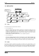
6.1 INSTALLATION
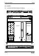
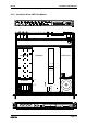
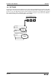
See the layout diagram for the correct locations of the boards, connectors and screws
6.1.1 Opening The PULSAR:
•
Unplug the power cord to switch off the P
ULSAR.
•
Unscrew the nine screws (Torx 10) holding the top cover.
•
Pull the top cover backwards and remove it.
•
Loosen the nine screws (Torx 10) holding the bottom cover.
•
Remove the bottom cover.
6.1.2 Opening The Converter:
•
Straighten the tabs of the tab/slot-fixing. Try to do this precisely.
•
Remove the cover of the RF amplifier of the converter. If a filter is already installed, follow the
instructions. Otherwise, go to the procedure
Installing the filter module
.
•
Unscrew the filter board.
•
Pull out the installed filter module.
•
In case of a VHF filter : also remove the two coaxial cables.
6.1.3 Installing The Filter Module
•
In case of a VHF filter: put the coax cables into the connectors of the new filter module.
•
Place the new filter module on the converter board. Be careful with the red connector on both
boards.
•
Fix the filter module with the two screws.
•
Fix the cover of the RF-amplifier by twisting back all the tabs to ensure good RF-shielding. Be care-
ful not to break the tabs.
6.1.4 Updating The Software Version
Persons working with the PULSAR should be grounded with a resistor isolated wrist
strap before touching the electronic components and before removing any assembly
from the unit.
• In case of the installation of an agile filter, the included eeprom U7 must be plugged in. Check the
layout diagram for the correct location.
INSTALLATION OF A CHANNEL FILTER OR
AN AGILE FILTER INTO THE PULSAR