R 9849999 INSTALLATION MANUAL Ceiling Mount for CLM series projector Date 26/11/07 Rev: 00 Art. No.
Due to constant research, the information in this manual is subject to change without notice. Produced by BARCO NV,Nov. 2007. All rights reserved. Trademarks are the rights of their respective owners. BARCO n.v. Noordlaan 5 B-8520 Kuurne Belgium Tel : +32/56/368211 Fax : +32/56/351651 E-mail : sales.bps@barco.com Visit Barco at the web: http://www.barco.
Safety guidelines WHO WARNING This installation manual must be performed by authorized technical personnel only. The ceiling should be capable of supporting a weight of at least 5 times the total weight of the Ceiling Mount and Projector (i.e. at least 160 kg or 353LB). If it cannot, the ceiling must be reinforced. Improper installation may result in serious personal injury. Consult a professional structural engineer prior to suspending the Ceiling Mount from a structure not intended for that use.
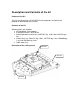
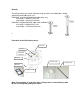
Description and Contents of the kit Purpose of the Kit The kit is designed for the CLM CM R10 series projectors and allows the projector to be mounted to the ceiling.
Remark: The ceiling mount can also be mounted using one of the 2 available bars (height adjustment) and cable cover assy. R9841260: short bar R822922 and cable cover assy . min length = 445mm(17.52 inch) max length = 810 mm(31.89 inch) R9841261: long bar R822923 cable cover kit R984 . min length = 845mm(33.27 inch) max length = 1210 mm(47.
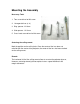
Mounting the Assembly Necessary Tools 1. Torx screw driver for M3 screw 2. Hexagonal driver (n° 6) 3. Ring spanner 12-13mm 4. Side spanner 12-13mm 5. Cross head screw driver for M8 screw Centering the ceiling mount Mark the position on the ceiling hole. Since the center of the lens does not coincide with the center of the projector, the center of the lens has been marked on the ceiling mount.
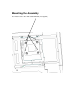
Mounting the Assembly The fixation can be done with standard M8 bolt (not supplied)
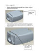
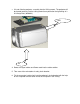
Projector preparation 1. Turn the projector to its back and remove the Feet assembly. Unscrew 3 Plastic feet and remove their Allen head M10 screws. Discard 3 plastic feet r852944 and x head M10 screw. R852944, R852945 & A566050 M10 SCREW, & FEET SUPPORT 2. Fix the Spacer M10 (r835785) as shown below. For alignment of the Centre distance between the spacers fix the ceiling mount and fix nut M8 B360623, Do not tight fully then tight the spacer M10. Remove the Ceiling mount and fix it on the Ceiling.
3. Lift and slide the projector assembly into the Ceiling mount. The projector will be located precisely into the ceiling mount base plate after the tightening of 3 M 8 flange Nuts (b360623). Slide Lift 4. Route the Signal cables and Power cord into the cable saddles. 5. Take care of the orientation of safety chain bracket. 6. Fix the one end of safety chain into the projector’s chain bracket with the help of the snap hook and the other end to the firm place in the Ceiling.
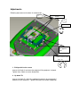
Adjustments Following adjustment can be done in random order. A Shift parallel to screen C Up/down B 4no’s (2 in opposite side) Rotate around central Axis ±3° 1. Shift parallel to the screen Loosen the 2 bolts A and move the projector till the projector is aligned. Tighten these 2 bolts to secure the position. 2. Up down Tilt Loosen the 4 bolts B . Adjust the up/down tilt precisely by moving bolt C clockwise or anti clockwise . Tighten the 4 bolts B to secure the position.
Rotate around vertical axis ±5° E F F G Rotate around central Axis ±3°
3. Rotate around central Vertical axis Loosen the 4 bolts E . Rotate/adjust the projector clockwise or anti clockwise. Tighten the 4 bolts E to secure the position. 4. Rotate around central Horizontal axis Loosen the 4 bolts F . Adjust the motion precisely by moving bolt G clockwise or anti clockwise. Tighten the 4 bolts F to secure the position.
Mounting the bar with Cable Cover assembly 1. Unscrew the 2 bolts J and slide out the upper part of the Bar. Pass the cable cover into the upper part of the Bar 2. Slide the horizontal shift plate R 826743 into the lower part of the Bar. Fix with 4 M8 bolt K. 3. Slide the upper bar into the lower bar assembly. Remount the 2 previously removed bolt J. Adjust the height to minimum.
4. Routing the Cables a. RGBHV cable preparation: With the help of PVC tape arrange the connectors in series. Pass the Signal cables and Power cord into cable guide R826761 . b. Pass the Signal cables into the IQ bar assembly from top side. Take out the BNC connector (in case of a 5 BNC cable) one by one from bottom side.
c. Pass the Power cord and the other cables (if any) one by one. d. Pass all the cables one by one from cable guide R 826745 and fix the cable guide on to the horizontal shift plate using 2 M3 Screws L. L The cable routing through IQ bar is complete. Adjust the approximate height of the IQ bar and also adjust the length of the cable required at the projector side. 5. Mount the Ceiling Bracket R 826748 on to the ceiling with standard M8 bolt not supplied with the Kit.
6. Hang on the IQ bar and cable routed assembly. Fix with 4 M8 bolt along with washer M. M 7. Mount the Ceiling mount assembly on to the horizontal shift plate by twisting and then lifting up. Fix the 2 M8 Bolt A. A 8. Route the Power cord to the back and Signal cables to the front.
There is also an option to route the cable from inside the Ceiling mount using cable ties and guiding holes on the Ceiling mount base as shown below. Cable Ties RGB cables Power cord & other cables Cable Tie Break the cable guide grooves on the cable cover as per the direction and location of the input cables and power cord at customer site/room.
9. The adjustment procedure for the rotation around central vertical axis can also be done as explained below. Loosen the 4 M3 screws N of cable cover and slide it down word. Loosen the 4 bolts O. Rotate /adjust the projector clockwise or anti clockwise. Tighten the 4 bolts O to secure the position. Slide up the cable cover and fix 4 M3 screws N. O O Rotate around R83578l 5 10. fix the one end of safety chain into the projector’s Eye bolt and the other end to the firm place in the ceiling.