DC Toolset User guide For DP series R59770449/01 15/12/2009
Barco nv Media & Entertainment Division Noordlaan 5, B-8520 Kuurne Phone: +32 56.36.89.70 Fax: +32 56.36.883.86 E-mail: sales.events@barco.com Visit us at the web: www.barco.
Changes Barco provides this manual ’as is’ without warranty of any kind, either expressed or implied, including but not limited to the implied warranties or merchantability and fitness for a particular purpose. Barco may make improvements and/or changes to the product(s) and/or the program(s) described in this publication at any time without notice. This publication could contain technical inaccuracies or typographical errors.
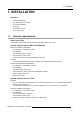
1. Installation 1. INSTALLATION Overview • • • • • • 1.1 General requirements Free download of DC Toolset DC Toolset installation Starting up Uninstall DC Toolset About this manual General requirements Before you begin It assumes you are familiar with the Windows operating system at your site.
1. Installation Recommended hardware specifications : • PC Pentium IV or equivalent, 2.4 GHz • 512 MB RAM • 140 MB hard disk free space • SXGA resolution (1280 x 1024) with 32 Mb video memory • Serial communication port • Ethernet connection Mac OS X Software • Apple’s Java SE 5.0 Release 3 or better • Mac OS X v10.4.
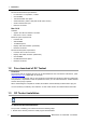
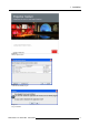
1. Installation 2. Double click on DCtoolset_Installer.exe . The installation starts. Depending on the local Internet Explorer settings, it is possible that a warning is displayed. Just click Run to start the installation. 3. Follow the instructions given in the different install windows. 4. Complete installation is automatic. Note: A restart of the computer is necessary before the software can be used.
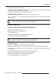
1. Installation Image 1-1 File properties Only DC Toolset framework is installed. To start using it, first install one or more device plug-ins. The software will request to install the plug-ins. 1.4 Starting up Launching DC Toolset on Microsoft Windows To start up the DC Toolset software: 1. Click on Start → Programs and select Barco → DC Toolset→ DC Toolset. Or, if a desk top icon is available, double click that desk top icon. The software starts up. This start up procedure can take a while.
1.
1. Installation 1.5 Uninstall DC Toolset How to uninstall on a Microsoft Windows platform To uninstall the program, normal Windows functionality can be used to remove a software. Click on Windows Start, select Settings and open Add/Remove software. Select the version of DC Toolset which must be removed and click on Remove. The complete program will be removed from the hard disk. How to uninstall on a Linux platform Remove the DC Toolset folder from the home folder.
2. Menus 2. MENUS Overview • • • • • 2.1 General Menu and button bar Main window Workspace Explorer About DC Toolset General The right mouse button The right mouse button is used in DC Toolset for direct controls. The use of this button can be handy throughout the complete software. Ergonomics DC Toolset works on the principle of windows with adjustable sizes that can be positioned as you like. When DC Toolset opens, it displays the main window along with the Menu and button bar.
2.
2. Menus Indication Description A Window title. Construction of active module - Configuration name B Menu C Module navigation buttons D Configuration preview pane E Log window. Can be hidden by the log information button on top of the configuration preview pane. F Settings pane. Content changes with the selected module button and selected projector/device.
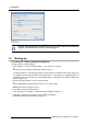
2. Menus press F11. Image 2-5 Workspace explorer What can be done The workspace explorer window gives an overview of the existing Configurations. To select a configuration, just click on it. The background of the selected configuration changes to blue. When the same item is open (active) the background remains blue. When another configuration is selected, the background of this new configuration becomes blue and the background of the active (open) configuration changes to orange.
2. Menus Image 2-6 About window System details Click on System details to see the system parameters on which DC Toolset is running.
2. Menus Module details Click on Module details to get an overview of the installed modules. Image 2-8 Module details First of all the software version and the release date are indicated in Module manager. Module details gives an overview of the installed modules and their version. Plug-in details Plug-in details gives an overview of the installed device plug-in together with their version.
2. Menus For more info about a device plug-in, click on the desired plug-in to select and then click on More info... . Image 2-10 More info device plug-in Release information, plug-in description and license agreement is given.
2.
3. Preferences 3. PREFERENCES Overview • • • • • • • 3.1 Introduction Start up the preferences Access level Software Appearance Bug report setup Logging Workspace selection Introduction Overview Preferences determine the default behavior of the software. Some preferences can be generally set for the complete software, some others are only for the different plug-in modules. 3.2 Start up the preferences How to start up ? 1. Click on File on the menu bar. (image 3-1) The file menu opens. 2.
3. Preferences Image 3-2 Preference window 3.3 Access level What can be done ? Some actions and functions of the DC Toolset are restricted to certain access levels. In this panel you can check the access level and read information from a dongle, if you have one. A dongle is not required to use the normal functions in DC Toolset.
3. Preferences 4 different levels are defined: • operator level • service technician level • theatre technician level • Barco technician level Each level can access specific functions in the service module. Only the operator level functions are described in this manual. 3.4 Software Appearance What can be changed ? The following items can be changed: • Language of the software. • Look and feel of the software. Language selection 1. Click on Appearance (image 3-2). The appearance window opens. 2.
3. Preferences The possible look and feels will be displayed. The following are possible: - Windows - Java - Nimrod - Tiny LAF Nimrod and Tiny LAF are collections of look and feels. If one of both are selected, the second line becomes available to select a typical look and file out of the collection. (image 3-6) An info window will be displayed to announce that the look and feel change will take place after restarting the software.
3. Preferences Use of specific fond 1. Click on Appearance (image 3-2). The appearance window opens. 2. Check the check box in front of Use specific font. (image 3-7) The drop down menu becomes available. 3. Click on the drop down box and select the desired font. 4. Click on Apply to confirm the selection. An info window will be displayed to announce that the look and feel change will take place after restarting the software. Image 3-7 Use of specific font 3.
3. Preferences This personal data will be incorporated in the bug report so that Barco can contact you. Personal data contains the following information : - First name - Last name - Organization - E-mail address - Telephone number - Mobile number 3. Click on Edit mail settings. The mail settings window opens. (image 3-10) 4. Fill out Your mail account settings.
3. Preferences Image 3-9 Bug report setup window Image 3-10 Mail setup window 3.6 Logging Start up 1. Click on Logging. The logging preferences window opens.
3. Preferences Image 3-11 Logging and debugging preferences Logging level Click on the slider bar to set the desired logging level. The following levels are possible: • Debug • Info • Error • Warning • Fatal Message to log file The logging about the behavior of the program can be logged in a file. Each time the program is started a new log file is created. The file is saved in a subdirectory log of the DC Toolset install directory.
3. Preferences Or, click on ... to open an Open dialog box (a2). 3. Browse to a workspace or enter a new workspace in the File name field. 4. Click on Open (b). The current configurations will be closed. 5. Click on Apply to apply the new workspace (c).
3.
4. Configurator 4. CONFIGURATOR Overview • • • • • • • • • • • 4.1 Introduction Configurator window Create a new configuration Add device to a configuration via scanning Add device to a configuration Reconnect a device Edit projector properties Configuration preview Configuration properties Preview layout properties General Settings Introduction Overview The configurator makes it possible to create configurations and to change the settings of each device separately.
4. Configurator 4.3 Create a new configuration Steps to be taken 1. Click File on the menu and select New → New configuration (a). (image 4-2) Or, press Ctrl + N. The New configuration dialog box opens (b). 2. Fill out a name for the new configuration next to Configuration name. The default name will be Configuration_’digit’ (c). Note: Only the characters a to z, A to Z, 1 to 9 and (, ), _, -, @ or allowed in a name.
4. Configurator The overview window gives the following items: • • • • • Device type Host name IP address MAC address Plug-in name How to add 1. Click Configuration on the menu and select Add device via scan... (1a). (image 4-3) Or, right click on a not connected projector in the preview pane to open the content menu and select Add device via scan.. .(1b) Or, press Insert key. A network scan is started and a device overview window is displayed (2a, 2b). 2.
4. Configurator 4.5 Add device to a configuration This chapter describes how to add a device, projector or touch panel to a configuration without scanning the complete network for all possible devices. Overview • • • • 4.5.1 Add device General properties Set up a Ethernet connection Decorator setup Add device The possible device types depends on the installed plug-ins.
4. Configurator Image 4-4 4.5.2 General properties Overview Click on the General tab to open the general properties if not yet open (a).
4. Configurator Projector’s identification The default display name is Barco followed by the projector type. This name can be changed to any other name. Click in the name field, select the current name and enter a new name (b). Next to the display name, the device type is indicate with the name and a device icon. Projector status Indicates the communication status of the projector (c). • • 4.5.
4. Configurator 4. Click OK to make the connection. Image 4-7 Create connection via host name Making a connection via a host name is only possible when the host name is known by the network DNS server. Via a device scan 1. Select the Connection properties tab (a). (image 4-8) The right pane changes to the connection setup page. 2. Click on the Device scan button (b). The Scanning projector progress bar appears.
4. Configurator Image 4-8 Batch connection 4.5.4 Decorator setup What is a decorator Decorator information is extra data about the projector which can be displayed in the configuration preview next to the projector pictograph.
4. Configurator Image 4-9 Decorator properties Decorator position The extra information can be place in the north, south, east or west of the projector pictograph. Click on the desired radio button to determine the decorator position. Decorator content The following information can be displayed in the configuration preview: • Projector name • Connection settings • Lamp shutter status • Active files • Device type 4.6 Reconnect a device Via the context menu 1.
4. Configurator 2. Open the device properties via right click and selecting Properties. Or, via click on Configuration on the menu and selecting Selected device → Properties (a). Or, by pressing Ctrl + Enter. The Device dialog box opens (b). 3. Click on Connection (c). The Connection tab opens (d). 4. Click on OK (e). The device tries to make a connection and to retrieve data (f). When it is successful the pictograph border becomes green, the properties are filled out.
4. Configurator 4.7 Edit projector properties Via the menu 1. Click on a projector to select (a). (image 4-12) 2. Click Configuration on the menu and select Selected device → Properties (b). Or, press Ctrl + Enter. The Properties dialog box opens (c). To edit the: - general properties. - connection properties. - decorator. see Add projector to a configuration. Image 4-12 Edit device properties via menu Via the context menu 1. Right click on a device graph in the configuration preview.
4. Configurator Image 4-13 Edit device properties via right click 4.8 Configuration preview Device status The border color around the pictograph indicates the device status. Green: device is online and there is communication with the device. Grey: device is offline. Red: device is online but there are warnings about the use of the device. Shaded: device is disabled. 4.9 Configuration properties What is available? The following properties are available: • author name.
4. Configurator 3. To add a description, click in the Description field and enter a description for the configuration (d). 4. Click OK to save and close the Configuration properties dialog box (e). Image 4-14 Configuration properties 4.10 Preview layout properties Overview • • • Background color Background image Rearrange pictographs in preview pane 4.10.1 Background color How to set background color 1. Right click in the preview pane but not on a pictograph (a). (image 4-15) A context menu opens. 2.
4. Configurator Tab swatches = way Via the swatches color dialog, step 6. 1 Tab HSB = way 2 Via the HSB color dialog, step 7. Tab RGB = way 3 Via the RGB color dialog, step 8. 6. Select the desired color (via swatches = predefined color samples). (image 4-16) The first selected color will be indicated in Recent. When others are selected for a preview, the color indication will also be added in the Recent list as first one.
4.
4. Configurator Image 4-18 Select color via RGB 4.10.2 Background image How to set background image 1. Right click in the preview pane but not on a pictograph (a). (image 4-19) A context menu opens. 2. Select Graph properties. The Graph properties dialog box opens (b). 3. Check the check box next to Use background image (c). 4. Fill out the complete path to the image (d1) and continue to step 6 Note: Only jpg, gif and png file are allowed. Or, click on ... (d2) An Open dialog box opens (d3) 5.
4. Configurator Image 4-19 Set background image 4.10.3 Rearrange pictographs in preview pane How to rearrange 1. Right click in the preview pane but not on a pictograph. (image 4-20) A context menu opens. 2. Select Rearrange graphs. The pictographs are rearranged in the preview pane.
4. Configurator 4.11 General Settings Overview Image 4-21 General settings DC projector Image 4-22 General settings Touch panel The General Settings pane is an read only pane and gives information about: • • • • device name device type serial number overview of device status For a touch panel, an extra Maintenance button is available.
5. General device settings Touch panel 5. GENERAL DEVICE SETTINGS TOUCH PANEL 5.1 Start up and overview How to start up 1. Click on the desired projector graph to display the touch panel properties. (image 5-1) 2. If the General settings are not open, click on the General tab. The general settings are displayed.
5. General device settings Touch panel 5.2 Add a custom logo in touch panel About a custom logo The touch panel software allows to place a custom logo on the upper left corner of the touch screen. The software provides an area of 90 x 90 pixels. Any image larger than 90 x 90 pixels will be proportionally scaled to match inside this area. The file must be a bitmap file (bmp, jpeg, jpg, png, ...). Current active logo To display the current active logo in DC Toolset, click on Reload.
5.
5. General device settings Touch panel Image 5-4 Change logo 5.3 Temporary account Why creating a temporary account If there are no root user defined on the touch panel or if these root users cannot be activated then it still possible to create a temporary root user via DC Toolset. This user has access to all functions and can create a new root user for the touch panel. This temporary account is mostly used for service purposes and will be deleted when the service actions are finished.
5.
5.
6. General device settings DC projector 6. GENERAL DEVICE SETTINGS DC PROJECTOR 6.1 Start up and overview How to start up 1. Click on the desired projector graph to display the projector general settings.
6.
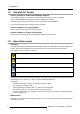
7. Installation 7. INSTALLATION Only for Touch panels. Overview • • • • • 7.1 Starting up the file management Create new folder Delete a file or folder Download a file from the touch panel Upload a file on the touch panel Starting up the file management How to start up 1. Click on the Installation tab to display the installation functions (a). (image 7-1) 2. Click on File Management (b). The File management window opens (c).
7. Installation About the file manager Only user files can be displayed or manipulated in the file manager. The following functions are available: 7.2 (1) Reload file list, to update the content of the file manager. (2) Create new folder (3) Delete file or folder (4) Download selected file (5) Upload file Create new folder What can be done ? A new folder can be created on the touch panel’s operating system. How to create a folder 1. Click on the New folder icon (a).
7. Installation 2. Click on the Delete icon. Image 7-3 Delete file or folder 7.4 Download a file from the touch panel What can be done ? Any user file stored on the touch panel can be downloaded to the computer. How to download 1. Browse in the File management window to the desired file or folder on the touch panel and click on it to select (a). (image 7-4) 2. Click on the Download icon (b). The Download window opens (c). 3.
7. Installation Image 7-4 Download file 7.5 Upload a file on the touch panel What can be done ? A file can be transferred from the computer to the touch panel and stored as user file. How to upload 1. Click on the Upload icon (a). (image 7-5) The Upload files window opens. 2. Click on the ... button (b) to open the browse window. 3. Browse to the desired file or folder and click Open. The full path is displayed in Files and folders selected for upload. 4.
7.
7.
8. Update module 8. UPDATE MODULE Overview • • • • 8.1 Introduction Update a Digital cinema projector Updating a touch panel Version info Introduction Overview The firmware of the projector/device can be updated with DC Toolset. Free downloadable packages can be found on Barco’s Partnerzone, (URL: https://my.barco.com). Registration is necessary. If you are not yet registered, click on Sign up my.barco and follow the instructions.
8. Update module 5. Browse to the to the directory where the update package is stored. The available packages for the connected projector are listed. - update package: use this package to upgrade the projector if the version info of the projector can be retrieved in a normal way. 6. Select the desired update (4) and click Select (5). The package is loaded in the update window (6). If you want to see more information about the update, click on More information ... (7) to display the release info.
8.
8.
8.
8.
8.
8. Update module 8.3 Updating a touch panel How to update 1. Click on Update. Device ID, serial number and communication info is given. 2. Click on Update now to start up the update wizard. (image 8-11) 3. If the indicated folder (a) is not the location where the update package is stored, click on ... (b) to open the browse dialog box and browse to the directory where the update package is stored. Click on Open. The available packages are listed.
8. Update module Image 8-11 Update wizard 8.4 Version info To get version info 1. Click on the Version info tab. 2. Click on the Refresh info button. Version info will be retrieved from the device and displayed in an overview window.
8. Update module Image 8-12 Version info Save the version info 1. Click first Reload now to have the latest info. 2. Click on Save ... A browse window opens. 3. Browse to the desired location, enter a file name and click on Save.
9. Diagnostic module 9. DIAGNOSTIC MODULE Overview • • • 9.1 Diagnostic start up Diagnostic for Touch panel Diagnostic for DP projectors Diagnostic start up Start up To start up the Diagnostics, click on the diagnostics icon ( Modules and select Diagnostics. ) on the navigation button bar or click on Image 9-1 Start Diagnostics module 9.2 Diagnostic for Touch panel Overview Actual diagnostics is not supported for Digital Cinema Touch panels.
9. Diagnostic module 9.3 Diagnostic for DP projectors Overview Image 9-2 Diagnostic overview Various information This part gives information about: • • • the projector run time since its first start up. Lamp run time, actual run time and remaining run time, expressed in digits, percentage and slide bar. number of lamp strikes since lamp was built in. Error Overview of possible errors. Temperatures Overview of measured temperatures.
A. Recovery a projector with special plug-in A. RECOVERY A PROJECTOR WITH SPECIAL PLUG-IN When can it be used? When something happens during the update process and the control software is damaged, use the recovery procedure to recover the projector. When the control software gets corrupt during normal operation, recover the projector via the recovering procedure. Do not use this recovery procedure if it is not really necessary ! A.1 Recovery preparations Overview 1. Start up DC Toolset. 2.
A. Recovery a projector with special plug-in Image A-2 Create configuration Image A-3 Add digital cinema projector Image A-4 Start updater A.2 Recovery procedure What should be done? The recovery of the software is done in different steps: 1. Recovery of the main software called dp80. 2. Reboot of the projector. 3. Updating all other software with intermediate reboot if necessary.
A. Recovery a projector with special plug-in If the code is entered correctly, the Projector Toolset Settings dialog opens otherwise retry this step. 2. Disable Check device type before update (both items must be disabled). (image A-5) 3. Click OK to close the dialog. 4. Click Update now. An update dialog window opens with the message that the projector is from an unknown type. (image A-6) 5. Click on the combo box and select the correct projector type. Click OK to continue.
A.
A.
A. Recovery a projector with special plug-in Image A-9 Uncheck all items except dp80 Update all other software 1. Click again on Update now. The update dialog window opens again with the message that the projector is from an unknown type (image A-6). 2. Click on the combo box and select the correct projector type. Click OK to continue. The Update package selection window opens (image A-7). 3. Select the package and click Next. Version information is collected again. All not updated software is checked. 4.
A. Recovery a projector with special plug-in Image A-10 Additional updates To check if the everything is updated, redo the procedure and check if there are still items checked in the lists. When there are still items checked, continue with the update procedure.