BARCO PROJECTION SYSTEMS GRAPHICS 8200 R9001330 OWNER'S MANUAL Art. No. :R5975288 Date: 110497 BARCO PROJECTION SYSTEMS GRAPHICS 8200 R9001330 OWNER'S MANUAL Date: 110497 Art. No.
Due to constant research, the information in this manual is subject to change without notice. Produced by BARCO NV, April 1997. All rights reserved. Trademarks are the rights of their respective owners. Printed in Belgium Due to constant research, the information in this manual is subject to change without notice. Produced by BARCO NV, April 1997. All rights reserved. Trademarks are the rights of their respective owners.
Table of Contents WARNINGS & SAFETY INSTRUCTIONS ....................................................................................................................................... 1-1 AVERTISSEMENTS & PRESCRIPTIONS DE SECURITE .............................................................................................................. 1-1 UNPACKING & DIMENSIONS ..............................................................................................................................................
Table of Contents RGB analog input module. ................................................................................................................................................... 7-6 Component input module. .................................................................................................................................................... 7-9 RGB3S/RG3sB input module. ..................................................................................................................
Table of Contents Gamma ............................................................................................................................................................................ Geometry ......................................................................................................................................................................... Shift ..................................................................................................................................
Table of Contents Hardwired RCU. .................................................................................................................................................................. 14-2 RCVDS 05 .......................................................................................................................................................................... 14-3 VS05 .........................................................................................................................
Safety Instructions WARNINGS AVERTISSEMENTS Safety instructions Prescriptions de securite On safety Securite On installation Installation On servicing Entretien et reparation On cleaning Nettoyage On repacking Re-emballage On illumination Eclairage 1-1 5975288 BARCOGRAPHICS 8200 110497 Safety Instructions WARNINGS AVERTISSEMENTS Safety instructions Prescriptions de securite On safety Securite On installation Installation On servicing Entretien et reparation On cleaning Nettoyage On repacking Re-emballa
Prescription de sécurtié Remarque sur la Sécurité DONNEES POUR LE PROPRIETAIRE Les projecteurs sont fabriqués conformément aux exigences des normes de sécurité internationales IEC950, UL 1950 et CSA C22.2 No. 950. Ces normes de sécurité sont imposées aux équipements de la technologie informatique incluant les équipements électriques. Le numéro de pièce et le numéro de série sont situés à l’arrière du projecteur. Copier ces numéros dans les espaces prévus ci-dessous.
Safety Instructions Notice on safety OWNER’S RECORD Projectors are built in accordance with the requirements of the international safety standards IEC950, UL 1950 and CSA C22.2 No. 950, which are the safety standards of information technology equipment including electrical business equipment. The part number and serial number are located at the rear of the projector. Record these numbers in the spaces provided below. Refer to them whenever you call upon your BARCO dealer regarding this product.
Prescription de sécurtié ATTENTION RISQUE D'ELECTROCUTION NE PAS OUVRIR ATTENTION : AFIN DE REDUIRE LE RISQUE DE CHOCS ELECTRIQUES, NE PAS ENLEVER LE COUVERCLE (OU LE DOS) IL N'Y A PAS DE PIECES REPARABLES PAR L'UTILISATEUR A L'INTERIEUR LE SERVICE NE PEUT ETRE EFFECTUE QUE PAR DU PERSONNEL QUALIFIÉ L’éclair avec une tête de flèche dans un triangle indique à l’utilisateur que les pièces à l’intérieur de l’appareil présentent un risque de chocs électriques.
Safety Instructions The lightning flash with an arrowhead within a triangle is intended to tell the user that parts inside this product are risk of electrical shock to persons. The exclamation point within a triangle is intended to tell the user that important operating and/or servicing instructions are included in the technical documentation for this equipment.
Prescription de sécurtié type avec terre. Ceci est une mesure de sécurité. Si le connecteur ne s’adapte pas dans la prise, contacter votre électricien pour Si cet équipement cause des interférences de radio ou de télévision, remplacer la prise non valable. Ne pas compromettre le but du l’utilisateur peut essayer de corriger les interférences en appliquant connecteur de terre.
Safety Instructions plug into the outlet, contact your electrician to replace your obsolete outlet. Do not defeat the purpose of the grounding-type if this equipment does cause interference to radio or television plug. reception, the user may try to correct the interference by one or more WARNING FOR THE CUSTOMERS: THIS APPARATUS MUST BE GROUNDED (EARTHED) via the supplied 3 conductor AC power of the following measures : cable. - Re-orientation of the receiving antenna for the radio or television.
Prescription de sécurtié * Pour débrancher le cordon, le tirer par le connecteur, jamais par le * Ne pas utiliser le projecteur à proximité d’eau. cordon lui-même. * N’utiliser que le cordon d’alimentation fourni avec votre projecteur.
Safety Instructions * To disconnect the cord, pull it out by the plug. Never pull the cord * Use only the power cord supplied with your projector. While appearing to be similar, other power cords have not been safety itself. tested at the factory and may not be used to power the projector. * If an extension cord is used with this product, make sure that the For a replacement power cord, contact your dealer.
Prescription de sécurtié * Laisser suffisamment d’espace autour du projecteur et ne pas Pièces de rechange - Lorsqu’on a besoin des pièces de rechange, obstruer la circulation de l’air. Ne pas mettre des feuilles libres ou veiller à ce que le technicien de service utilise des pièces d’origine BARCO ou des pièces équivalentes autorisées qui ont les mêmes d’autres objets plus près de 11 cm du projecteur. caractéristiques que la pièce d’origine BARCO.
Safety Instructions * Do not block the projector cooling fans or free air movement under Replacement parts - When replacement parts are required, be sure and around the projector. Loose papers or other objects may not be the service technician has used original BARCO replacement parts or authorized replacement parts which have the same characterisnearer to the projector than 4" on any side. tics as the BARCO original part.
Prescription de sécurtié Pour garantir les meilleures performance et définition, les objectifs de projection sont spécialement traités avec un revêtement anti-reflets. En conséquence : éviter de toucher les objectifs. Pour enlever la poussière de l’objectif, utiliser un chiffon sec et doux. Ne pas utiliser de chiffon humide, de solution détergente ou de diluant. Respecter la méthode de nettoyage des objectifs indiquée dans l’annexe D au manuel d'utilisateur.
Safety Instructions To ensure the highest optical performance and resolution, the On illumination projection lenses are specially treated with an anti-reflective coating, therefore : avoid touching the lens. To remove dust on the lens, use In order to obtain the best quality for the projected image, it is essential a soft dry cloth. Do not use a damp cloth, detergent solution, or thinner.
Unpacking & Dimensions UNPACKING DIMENSIONS BATTERY INSTALLATION ON THE RCU 5975646 BARCOGRAPHICS 8100 090296 2-1 Unpacking & Dimensions UNPACKING DIMENSIONS BATTERY INSTALLATION ON THE RCU 5975646 BARCOGRAPHICS 8100 090296 2-1
Unpacking & Dimensions Unpacking To open the banding, pull on the clip as shown in the first drawing. Pull To open Take the projector out of its shipping carton and place it on a table. For transportation, the projector is mounted on a wooden board with 3 bolts. Use a 13 mm wrench to remove these bolts. When using the projector as a table mounted configuration, always mount the 3 supporting feet (see drawing below). These feet are mounted on the same wooden board.
Unpacking & Dimensions Projector dimensions (units : mm) L Some examples of lenses : Name lens (*) L min mm(inch) L max mm(inch) HD(1.2:1) HD(2.2:1) HD(3.3:1) HD(3.9:1) HD(5:1) HD(7:1) HD(1.5-3:1) 1072 1043 1017 1022 1082 1252 1325 1087 1070 1072 1162 1202 1372 1355 (42.20) (41.06) (40.04) (40.24) (42.60) (49.29) (52.17) (42.79) (42.12) (42.20) (45.75) (47.32) (54.02) (53.
Unpacking & Dimensions Battery installation in the RCU. A battery (not yet installed to save the battery life time) is delivered inside the plastic bag with the power cord. To install the battery, remove the battery cover on the backside of the remote control by pushing the indicated handle a little to the bottom of the RCU. Lift up the top side of the cover at the same time (fig. 1).
Installation Guidelines INSTALLATION GUIDELINES Environment What about ambient light? Which screen type? What image size? How big should the image be? Where to install the projector? How to install the projector? 3-1 5975288 BARCOGRAPHICS 8200 110497 Installation Guidelines INSTALLATION GUIDELINES Environment What about ambient light? Which screen type? What image size? How big should the image be? Where to install the projector? How to install the projector? 5975288 BARCOGRAPHICS 8200 110497 3-1
Installation Guidelines Installation guidelines Careful consideration of things as image size, ambient light level, projector placement and type of screen to use are critical to the optimum use of the projection system. Max. ambient temperature : 40°C. * Environment Do not install the projection system in a site near heat sources such as radiators or air ducts, or in a place subject to direct sunlight, excessive dust or humidity.
Installation Guidelines * Which screen type? There are two major categories of screens used for projection equipment. Those used for front projected images and those for rear projection applications. Screens are rated by how much light they reflect (or transmit in the case of rear projection systems) given a determined amount of light projected toward them. The ‘GAIN’ of a screen is the term used. Front and rear screens are both rated in terms of gain.
Installation Guidelines * Where to install the projector? Inputs and computer video format input compatibility : Definitions of the Abbreviation on drawings Some examples : B = Distance between ceiling and top of the screen or between floor and bottom of the screen. A = Correction value, distance between bottom side of projector and middle of the lens. Value to be subtracted from B to obtain the correct installation position.
Installation Guidelines Ceiling mounting of the BARCOGRAPHICS 8200 Table mounting of the BARCOGRAPHICS 8200 Ce il in g CD B A PD Optical axis p rojection lens CD = B - A SH Pr o je c t o r S c re e n Screen Proje ct or SH CD = B - A Optical axis projection lens B SI DE VI EW PD A CD Fl oo r SI DE V IE W SW Screen Screen SW B O TTO M V I E W TO P V I E W Ceil ing SW SH SH SW B AC K V IE W Flo o r BA CK V IE W 3-5 5975288 BARCOGRAPHICS 8200 110497 Installation Guidelines Ceilin
Installation Guidelines * How to install a projection lens? The BARCOGRAPHICS 8200 is supplied without any lens. The following lenses are available as an option : HD(1.2:1) HD(2.2:1) HD(3.3:1) HD(4.0:1) HD(5:1) HD(7:1) HD(1.5-3:1) HD(3.0-5.3:1) WHD(3.5:1) BARCO ceiling support. Order number : R9829620 or R9829621 Always use the BARCO ceiling support to attach your BARCOGRAPHICS 8200 to the ceiling. The installation instruction for this support is enclosed in the packet of the set.
Installation Set Up INSTALLATION SET UP Projector configuration 4-1 5975288 BARCOGRAPHICS 8200 110497 Installation Set Up INSTALLATION SET UP Projector configuration 5975288 BARCOGRAPHICS 8200 110497 4-1
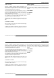
Installation Set Up The BARCOGRAPHICS 8200 can be installed to project images in four different configurations : front/table, front/ceiling, rear/table and rear/ceiling. Rear/Ceiling Front/Ceiling Rear/Table Front/Table 4-2 5975288 BARCOGRAPHICS 8200 110497 Installation Set Up The BARCOGRAPHICS 8200 can be installed to project images in four different configurations : front/table, front/ceiling, rear/table and rear/ceiling.
Installation Set Up To change the Configuration, enter the adjustment mode by pushing ADJUST or ENTER. Highlight Installation by pushing the control disk up or down and press ENTER to select. The installation menu will be displayed. ENTER displays the Installation menu. EXIT returns to operational mode. ADJUSTMENT MODE Select a path from below : GUIDED RANDOM ACCESS INSTALLATION SERVICE Source 01 Select with or then to return.
Location and Functions of Control LOCATION AND FUNCTION OF CONTROLS Front panel terminology Local keypad Remote control 5-1 5975288 BARCOGRAPHICS 8200 110497 Location and Functions of Control LOCATION AND FUNCTION OF CONTROLS Front panel terminology Local keypad Remote control 5975288 BARCOGRAPHICS 8200 110497 5-1
Location and Functions of Control Front panel terminology PR O J EC T O R MO DE : D I A G NO S T I C S CODE I R -R E CE I V E R G RE EN - O PERAT IO N C O M MU N IC AT IO N P O R T RS232 OUT RS 2 3 2 I N (8 00 -P ER IP HE RA LS ) RED - S T AND BY T his devic e com plies wit h P ar t 15 of t he F CC r ules .
Location and Functions of Control Control Panel Terminology a. Local keypad Getting access The keypad is located behind a door, screened with the name of the projector. To open the door, push once on the indicated side of the door and turn it to the front side of the projector. 9 7 0 8 5 6 3 4 1 2 b. Remote control This remote control includes a battery powered infrared (IR) transmitter that allows the user to control the projector remotely.
Location and Functions of Control 15 Remote Control (RCU) Local keypad 14 1 15 4 2 3 4 14 EXIT 13 ENTER 12 ADJ STBY 5 PAUSE TEXT HELP - ? 11 FREEZ 10 + PHASE 9 6 9 7 0 0 - 7 8 - 5 6 - 3 4 1 2 9 13 EXIT ST ANDBY 12 8 7 E NT E R + SHARPNESS + COLOR 5 5 6 TEXT 3 4 SHARPN T INT BRIG HTN 1 2 P HA S E COLOR CO NT RAST PAUSE 10 8 + TINT + - BRIGHTNESS + - CONTRAST 8 9 7 32a 5-4 5975288 BARCOGRAPHICS 8200 110497 Location and Functions
Location and Functions of Control Terminology 1 Back light key : when activated, all keys will be lighted up and visible in the dark. 2 ADJ. : ADJUST key, to enter the adjustment mode or for quick exit in the adjustment mode. 3 4 5 6 7 8 9 Address key (sunk key), to enter the address of the projector (between 0 and 9). Press the sunk address key with a pencil, followed by pressing one digit button between 0 and 9. STBY : stand by button - to start projection when the power switch is switched on.
Power Connection POWER CONNECTION 6-1 5975288 BARCOGRAPHICS 8200 110497 Power Connection POWER CONNECTION 5975288 BARCOGRAPHICS 8200 110497 6-1
Power Connection Power (mains) cord connection Use the supplied power cord to connect your projector to the wall outlet. Plug the female power connector into the male connector at the front of the projector. The power input is auto-ranging from 100 to 240 VAC. This projector may be connected to an IT-power system. PROJECTOR MODE : GREEN - OPERATION Fuses COMMUNICATION PORT RS 232 IN Warning For continued protection against fire hazard : - replace with the same type of fuse.
Power Connection When switching on with the power switch, the projector starts in the stand by mode. The projector mode indication lamp is red. To start image projection : a. press the 'Stand by' button on the local keypad or on the remote control. The projector mode indication lamp will be green.
Power Connection When the total run time of the lamp is 970 hours or more, the following message will be displayed for 1 minute. This message will be repeated every 30 minutes. Press EXIT to remove the message before the minute is over. When the total run time of the lamp is 1000 hours or more, the following message, with the exact run time is displayed on the screen. Lamp run time 980 h Lamp run time is 1000 hours. Operating the lamp longer than 1000 hours may damage the projector.
Connections INPUT MODULE CONNECTIONS Module insertion into the projector. Video/S-Video input module RGB analog input module Component input module RGB3S/RG3sB input module Peripheral equipment connection Connecting a computer Connecting a RCVDS05 Connecting a VS05 Connecting an IR Remote Receiver 800 7-1 5975288 BARCOGRAPHICS 8200 110497 Connections INPUT MODULE CONNECTIONS Module insertion into the projector.
Connections Input connections. The projector has modular input facilities. The input slots can be filled up with the following modules : DIAGNOSTICS CODE IR- RECEI VER Video, S-video (PAL, SECAM, NTSC) input order no. R9827900 RGBS/RGsB analog input order no. : R9827910 RGB3S/RG3sB input order no. : R9827920 Component Video input order no.
Connections Video/S-video input module 98 2790 AUDIO On On To the Video input : Composite video signals from a VCR, OFF air signal decoder, etc... 1 x BNC 1.0Vpp ± 3 dB VID EO/S-VIDEO INPUT To the S-Video input : Separate Y-luma/C-chroma signals for higher quality playback of Super VHS-signals. 1 x 4 pins plug (mini DIN) pin configuration : 1 ground luminance 2 ground chrominance 3 luminance 1.
Connections Push the Control disk up or down to highlight Installation and press ENTER to display the Installation menu. EXIT returns to operational mode. ADJUSTMENT MODE Select a path from below : GUIDED RANDOM ACCESS INSTALLATION SERVICE Use the control disk to select Input Slots by pushing it up or down and press ENTER. The internal system will scan the inputs and displays the result in the Input Slots menu. Source 01 Select with or then to return.
Connections Straps on module level. Floating or non-floating input. Video input : J11 : strap "yes" : non floating strap "no" : floating S-Video input : J12 : strap "yes" : non floating strap "no" : floating J13 : strap "yes" : non floating strap "no" : floating J12 J13 J11 Factory preset : strap on, input non floating. Non-Floating Floating Floating or non floating input 7-5 5975288 BARCOGRAPHICS 8200 110497 Connections Straps on module level. Floating or non-floating input.
Connections RGBS/RGsB analog : 5 x BNC Red : 0.7 Vpp ± 3 dB RGB analog input terminals with separate Horizontal and Vertical Blue : 0.7 Vpp ± 3 dB sync inputs(RGB-HV), with Composite sync input(RGB-S) or with Green : 0.7 Vpp ± 3 dB Sync signals on green(RGsB). 1 Vpp ± 3 dB if sync on green Vert. sync : 1 Vpp to 4 Vpp ± 3 dB Always use an interface when a computer and local monitor have to Hor. sync / Composite sync : be connected to the projector.
Connections RGB input selection : J8 Sync selection Separate sync Sync on green Key in the corresponding slot number on the RCU or the local keypad. Straps on module level : Floating or non-floating input.
Connections Push the control disk up or down to select Installation and press ENTER. ADJUSTMENT MODE Select a path from below : GUIDED RANDOM ACCESS INSTALLATION SERVICE Use the control disk to select Input Slots by pushing up or down and press ENTER. The internal system will scan the inputs and displays the result in the Input Slots menu. Source 01 Select with or then to return.
Connections Connect your component signals (Y-luma, R-Y and B-Y), e.g. a professional VCR to the Component input module. Component video : 4 x BNC R-Y : 0.7 Vpp ± 3 dB B-Y : 0.7 Vpp ± 3 dB Y : 0.7 Vpp ± 3 dB 1 Vpp ± 3 dB if Tri-level sync on green Composite sync : 1 Vpp to 4 Vpp ± 3 dB 98 2 Component input module. On CO MP ONE NT VI DE O I NP UT All input signals are always 75 ohm terminated, even the module is "not selected".
Connections Component input selection : Floating or non floating input Non-Floating Key in the corresponding slot number on the RCU or the local keypad.
Connections RGB3S/RG3sB input module. R G B H/C V 98 27920 Connect your RGB signals with Tri-level sync, e.g. a professional VCR to the RGB 3 level sync input module. RGB3S/RG3sB analog : 5 x BNC Red :0.7 Vpp ± 3 dB Blue : 0.7 Vpp ± 3 dB Green : 0.7 Vpp ± 3 dB 1 Vpp ± 3 dB if Tri-level sync on green Vert. Tri-level sync : 1 Vpp to 4 Vpp ± 3 dB Hor. Tri-level sync / Composite Tri-level sync: 1 Vpp to 4 Vpp ± 3 dB On RG B 3-L EVEL SYNC INPUT Vert. 3 level sync Hor.
Connections Straps on module level : Floating or non-floating input. Red : J3 : strap "yes" : non floating Green : J4 : strap "yes" : non floating Blue : J5 : strap "yes" : non floating H/C : J6 : strap "yes" : non floating V: J7 : strap "yes" : non floating J8 Sync selection Separate sync Sync on green strap "no" : floating strap "no" : floating strap "no" : floating strap "no" : floating strap "no" : floating Factory preset : strap "yes", non floating input Sync selection.
Connections Connecting a computer, e.g. IBM PC (or compatible), Apple Macintosh to the RS 232 input of the projector. R R DI AGNO STI CS CO DE I R- RE C EI VE R T hi s d ev ic e c ompl i es w i th P a rt 1 5 o f th e F CC ru le s .
Connections Connecting a RCVDS 05 to the projector. Connecting an IR Remote Receiver 800 to the projector. - Up to 10 or 20 inputs(video) with the RCVDS 05 and 90 inputs when RCVDS's are linked via the expansion module. - Serial communication with the projector. - Remote control buttons on the RCVDS to control the projector (source selection and analog settings). - The selected source number will be displayed on a 2 digit display and the selected input module will be indicated with a LED on the rear.
Controlling CONTROLLING How to use the RCU. Projector address How to display a projector address. How to program an address into the RCU. Picture controls with direct access. 8-1 5975288 BARCOGRAPHICS 8200 110497 Controlling CONTROLLING How to use the RCU. Projector address How to display a projector address. How to program an address into the RCU. Picture controls with direct access.
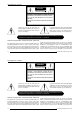
Controlling The BARCOGRAPHICS 8200 can be controlled with a. the RCU b. the hardwired RCU (cable is not included) c. the local keypad. b) RCU used in a hardwired configuration. Controlling the projector with the RCU and the hardwired RCU is equal. DIAGNOSTICS CO DE IR -R ECE IV ER T hi s d e v ic e c o mp l ie s w i t h P ar t 1 5 o f t h e F C C r ul e s.
Controlling c) Point the front of the RCU directly at one of the IR sensors of the projector. IR s e ns o r a. Software set up of the projector address. IR s e ns o r Ce ilin g Projector address See 'Change projector address' in chapter 'Service mode'. IR- RECEIVED 0 DIAGNOSTICS IR- ACKNOWLEDG ED CODE I IR- RECEIVER T a b le F ro nt o f projec to r R ea r o f p ro je c to r Every projector requires an individual address between 0 and 255 which can be set in the Service mode.
Controlling How to display a projector address? Press the ADDRESS key (recessed key on the RCU) with a pencil. The projector's address will be displayed in a 'Text box'. This text box disappears after a few seconds. To continue using the RCU, it is necessary to enter the same address with the digit buttons (address between 0 and 9). For example : if the Address key displays projector address 003, then press "3" digit button on the RCU to set the RCU's address to match the projector's address.
Controlling Contrast Control Tint Control A correct 'contrast' setting is important for good image reproduction. Adjust the contrast to the level you prefer, according to room lighting conditions. Use the + button for a higher contrast. Use the - button for lower contrast. Tint is only active for Video and S-Video when using the NTSC 4.43 or NTSC 3.58 system. Use the + button Use the - button. Sharpness Control. Color Saturation Use the + button for a sharper picture.
Start Up of the Adjustment Mode START UP OF THE ADJUSTMENT MODE 9-1 5975288 BARCOGRAPHICS 8200 110497 Start Up of the Adjustment Mode START UP OF THE ADJUSTMENT MODE 5975288 BARCOGRAPHICS 8200 110497 9-1
Start Up of the Adjustment Mode Adjustment Mode All source set ups, picture tunings and geometry are made while in the 'Adjustment mode' . Press the ADJUST or ENTER key to enter the 'Adjustment mode'. You are now in the 'Adjustment mode'. The control stick (RCU) or '+ or '-' keys (local keypad) are used to make menu selections and also for adjustments. The ENTER and EXIT keys are used to move forward and backward through the menu structure.
Start Up of the Adjustment Mode Some items in the Adjustment mode are password protected. While selecting such an item, the projector asks to enter your password (Password protection is only available when the password strap on the controller module is ON, see 'Change password' in chapter 'Service mode'. Your password contains 4 digits. Enter the digits with the numeric keys. Example : 2 3 1 9 The first digit position is highlighted. Enter with the numeric keys.
Guided Adjustment Mode GUIDED ADJUSTMENT MODE 10-1 5975288 BARCOGRAPHICS 8200 110497 Guided Adjustment Mode GUIDED ADJUSTMENT MODE 5975288 BARCOGRAPHICS 8200 110497 10-1
Guided Adjustment Mode The Guided Adjustment Mode is not active. ADJUSTMENT MODE Select a path from below : GUIDED RANDOM ACCESS INSTALLATION SERVICE Source 01 Select with or then to return. 10-2 5975288 BARCOGRAPHICS 8200 110497 Guided Adjustment Mode The Guided Adjustment Mode is not active. ADJUSTMENT MODE Select a path from below : GUIDED RANDOM ACCESS INSTALLATION SERVICE Source 01 Select with or then to return.
Random Access Adjustment Mode RANDOM ACCESS ADJUSTMENT MODE File Service Picture Tuning Geometry 11-1 5975288 BARCOGRAPHICS 8200 110497 Random Access Adjustment Mode RANDOM ACCESS ADJUSTMENT MODE File Service Picture Tuning Geometry 5975288 BARCOGRAPHICS 8200 110497 11-1
Random Access Adjustment Mode Starting up the Random Access Adjustment Mode ADJUSTMENT MODE Push the control disk up or down to highlight 'Random Access' and then press ENTER. Select a path from below : GUIDED RANDOM ACCESS INSTALLATION SERVICE Source 01 Select with or then to return. RANDOM ACCESS ADJUSTMENT MODE FILE SERVICE PICTURE TUNING GEOMETRY Select with or then to return.
Random Access Adjustment Mode File service Before using a new source, a correct file has to be installed. The projector's memory contains a list of files corresponding to the most used sources. When the new source corresponds with one of these files, the file can be loaded and saved for future use. When there is a little difference, the file can also be loaded and than edited until the source specs are reached. File annotation : xxxxxxxx.
Random Access Adjustment Mode Load file Push the control disk up or down to select LOAD and press ENTER to display the Load menu. The Load menu displays the corresponding files depending on the installed filter. This filter can be "Fit" or "All". To change the filter, push the control disk to the right to select "filter list" (filter list will be hightlighted) and press ENTER to toggle the annotation between brackets. "All" : all files that can be loaded will be displayed.
Random Access Adjustment Mode Edit file The Edit file menu makes it possible to change the settings of the file according to the real settings of the connected source. Consult the source specification before entering the data. To start up the EDIT menu, push the control disk up or down to select EDIT in the FILE menu and press ENTER. Select the file which must be edited (mostly the active file) and press ENTER. The Edit file adaptation menu will be displayed.
Random Access Adjustment Mode up or down to scroll to desired digit. When finished press ENTER to of the projected image. This value is normally given in the specification of the source. If not, adjust until full image height is displayed (no confirm. c. counting up or down by pushing the control disk to the right or to missing lines) the left.
Random Access Adjustment Mode Options Source number : The source number of a non-active source can be changed to any other source number. This makes it possible to create a file for future source numbers. EDIT FILE OPTIONS Source number 1 Clamp position [leading] Clamp delay 0 Clamp width 10 Field polarity [pos] Field select [both] Vertical refresh [sync] Vert.
Random Access Adjustment Mode Vertical refresh [sync/async] : The way of updating the image information on the LCD panels. For moving images, the vertical refresh has to be done on a synchronous way, for still images, asynchronous vertical refresh is possible. Vertical sync polarity : [leading] or [trailing] The vertical refresh can be synchronised with the leading sync edge or trailing sync edge. Default on [leading].
Random Access Adjustment Mode Rename To change the name of a selected file. Use the control disk to select RENAME and press ENTER. The Rename selection menu will be displayed. Use the control disk to select a file name and press ENTER to select. The Rename menu will be displayed with the selected file name already filled in in the 'From file name :' area and in the 'To file name:' area. FILE SERVICE LOAD EDIT RENAME COPY DELETE OPTIONS Select with or then to return.
Random Access Adjustment Mode Copy FILE SERVICE To copy a selected file into a new file. Use the control disk to select COPY and press ENTER. The Copy selection menu will be displayed. Use the control disk to select a file name and press ENTER to select. The Copy menu will be displayed with the selected file name already filled in in the 'From file name :' area and in the 'To file name :' area. LOAD EDIT RENAME COPY DELETE OPTIONS Select with or then to return.
Random Access Adjustment Mode Delete FILE SERVICE To delete a selected file out of the list of files. Use the control disk to select DELETE and press ENTER. The delete selection menu will be displayed. Push the control disk up or down to select a file and press ENTER. If [All] is selected, your password has to be entered before all files will be deleted. LOAD EDIT RENAME COPY DELETE OPTIONS Select with or then to return.
Random Access Adjustment Mode File Options FILE SERVICE Use the control disk to select OPTIONS and press ENTER. The option selection menu will be displayed. Press ENTER to toggle between [name] and [index] [name] : The files in the file list will be sorted on the file name. [index] : The files in the file list will be sorted on the file extension. LOAD EDIT RENAME COPY DELETE OPTIONS Select with or then to return.
Random Access Adjustment Mode Sync slow/fast PICTURE TUNING Highlight sync by pushing the control disk up or down and press ENTER to toggle between SLOW and FAST. SYNC [SLOW] STILL VIDEO [ON] COLOR BALANCE GAMMA Note : Sync is normally used in the SLOW position. The FAST position is used to compensate for unsteady sync pulses from older video playback equipment. Select with or then to return. Still Video PICTURE TUNING This function is only used for stationary interlaced images.
Random Access Adjustment Mode Color Balance PICTURE TUNING Highlight Color Balance by pushing the control disk up or down and press ENTER to select the color balance selection menu. SYNC : SLOW STILL VIDEO : ON COLOR BALANCE GAMMA The next choices are possible : Fixed color balance : - 3200 K (reddish) - 6500 K (white) - 9300 K (bluish) Select with or then to return. COLOR BALANCE Fixed color balance 3200 6500 9300 Custom white balance Select with , , then to return.
Random Access Adjustment Mode Gamma PICTURE TUNING With the gamma correction adjustment, it is possible to bring the details in dark image parts more to the front (lower image values) or to reduce the importance of these details (higher gamma values). To change the gamma value, highlight Gamma by pushing the control disk up or down and press ENTER. SYNC [SLOW] STILL VIDEO [ON] COLOR BALANCE GAMMA Select with or then to return. GAMMA 2.
Random Access Adjustment Mode Geometry Highlight Geometry by pushing the control disk up or down and press ENTER to select the geometry selection menu. The following adjustment are possible : - horizontal and vertical image shift. - horizontal and vertical image size - side keystone (only necessary if the projector is mounted under a non standard projection angle). - blanking - options RANDOM ACCESS ADJUSTMENT MODE FILE SERVICE PICTURE TUNING GEOMETRY Select with or then to return.
Random Access Adjustment Mode Size GEOMETRY Highlight Size by pushing the control disk up or down and press ENTER to select. SHIFT SIZE SIDE KEYSTONE BLANKING OPTIONS Select with or then to return. The size can be adjusted in a vertical or horizontal way. When adjusting the vertical size, for table mount configuration : the upper side of the image is fixed and only the lower side can be moved to its exact position.
Random Access Adjustment Mode Side keystone GEOMETRY Highlight Side Keystone by pushing the control disk up or down and press ENTER to select. The side keystone adjustment is used to align the image if the projector is mounted as a non standard projection angle. SHIFT SIZE SIDE KEYSTONE BLANKING OPTIONS Select with or then to return. Push the control disk to the right or to the left to adjust the keystone of the image.
Random Access Adjustment Mode Blanking GEOMETRY Highlight Blanking by pushing the control disk up or down and press ENTER to select. SHIFT SIZE SIDE KEYSTONE BLANKING OPTIONS Blanking adjustments affect only the edges of the projected image and are used to frame the projected image on to the screen and to hide or black out unwanted information (or noise). A 0% on the bar scale indicates no blanking. Select with or then to return.
Random Access Adjustment Mode Adjustment of the blanking on the of the image BLANKING TOP BOTTOM LEFT RIGHT Adjustment of the blanking on the bottom of the image Correct by pushing the control disk up or down Select with or then to return.
Random Access Adjustment Mode Options GEOMETRY Highlight Options by pushing the control disk up or down and press ENTER. The Geometry Options menu will be displayed. The next question will be asked by the projector : 'Use the same side keystone correction for all files ? [YES] or [NO]. [YES] : the same keystone correction will be used for all installed files. [NO] : the keystone has to be adjusted file per file. Push the ENTER key to toggle between [YES] or [NO]. Press EXIT to return to the Geometry menu.
Installation INSTALLATION Convergence Configuration Internal Patterns 12-1 5975288 BARCOGRAPHICS 8200 110497 Installation INSTALLATION Convergence Configuration Internal Patterns 5975288 BARCOGRAPHICS 8200 110497 12-1
Installation Starting up the Installation Mode ADJUSTMENT MODE Push the control disk up or down to highlight Installation and then press ENTER. ENTER continues to the Installation mode selection menu. EXIT returns to operational mode. Select a path from below : GUIDED RANDOM ACCESS INSTALLATION SERVICE Source 01 Select with or then to return.
Installation Input Slots Highlight Input Slots by pushing the control disk up or down and press ENTER. The internal system will scan the input slots and displays the result in the Input Slots menu.
Installation Convergence INSTALLATION Highlight "Convergence" by pushing the control disk up or down and press ENTER to display the convergence selection menu. Every LCD panel has 6 adjustment screws. By turning these screws you change the relative position of the panels and converge the image. Always start with the adjustment of the green panel. When the green image is correctly focused, it will later on be used as the reference image to converge the red and blue image.
Installation To adjust the convergence, there are test patterns provided in the convergence menu. Use the control disk to hightlight Convergence and press ENTER to display the Convergence menu. Start with the Green test pattern and continue with the Red on green and finish with the Blue on green. Use the control disk to select Green and press ENTER to display the green pattern. CONVERGENCE GREEN BLUE ON GREEN RED ON GREEN HATCH Select with or then to return.
Installation The three alignments influence each other, therefore repeat if necessary the above three steps (b,c and d). When the green pattern is correctly focused, press EXIT to return to the Convergence menu. Red on green convergence. Use the control disk to hightlight Red on green and press ENTER to display the Red on green test pattern. CONVERGENCE GREEN BLUE ON GREEN RED ON GREEN HATCH Select with or then to return. The longest lines are the red lines.
Installation If both lines are correctly converged, continue with screw 4. Adjust screw 4 until line 4 is correctly converged. It is possible that line 2 and 3 have to be reconverged. If so, repeat procedure for screw 2 and 3 (step b and c) If line 2, 3 and 4 are converged, continue with line 1 (screw 1). When line 1 is converged, check again the convergence of lines 2, 3 and 4. If necessary repeat the above procedure for the corresponding lines. Check if lines 5 and 6 are correctly converged.
Installation Blue on green convergence. Use the control disk to highlight Blue on green and press ENTER to display the Blue on green test pattern. Repeat the same procedure as for Red on green lines but read blue when red is indicated. CONVERGENCE GREEN BLUE ON GREEN RED ON GREEN HATCH Select with or then to return. To check the result of the convergence adjustments, highlight Hatch and press ENTER. A hatch pattern will be displayed on the screen. ENTER : displays a hatch pattern.
Installation Configuration INSTALLATION Highlight "Configuration" by pushing the control disk up or down and press ENTER to select. INPUT SLOTS CONVERGENCE CONFIGURATION INTERNAL PATTERNS For more information, see Projector configuration in chapter Installation Set Up. Select with or then to return. Internal Patterns The projector is equipped with different internal patterns which can be used for measurment purposes.
Service Mode SERVICE MODE Identification Change Password Change Language Change Projector Address Change Baudrate PC Reset Lamp Run Time Lamp Run Time History Panel Adjustments Preset Color Balance I²C Diagnosis 13-1 5975288 BARCOGRAPHICS 8200 110497 Service Mode SERVICE MODE Identification Change Password Change Language Change Projector Address Change Baudrate PC Reset Lamp Run Time Lamp Run Time History Panel Adjustments Preset Color Balance I²C Diagnosis 5975288 BARCOGRAPHICS 8200 110497 13-1
Service Mode Starting up the Service Mode ADJUSTMENT MODE Push the control disk up or down to highlight Service and then press ENTER. Some items in the Service mode are password protected (when the password function is active). Enter your password to continue. All other password protected items are now available if you stay in the adjustment mode. The service menu is built-up in two parts which are connected together with the 'more' item.
Service Mode SERVICE IDENTIFICATION CHANGE PASSWORD CHANGE LANGUAGE CHANGE PROJ. ADDRESS CHANGE BAUDRATE PC RESET LAMP RUNTIME LAMP RUNTINE HISTORY MORE... Select with or then to return. BARCO GRAPHICS 8200 CHANGE PASSWORD CHANGE LANGUAGE Enter new password 0000 ENGLISH Select with or then to return. Select with or then to return. CHANGE PROJ.
Service Mode SERVICE IDENTIFICATION CHANGE PASSWORD CHANGE LANGUAGE CHANGE PROJ. ADDRESS CHANGE BAUDRATE PC RESET LAMP RUNTIME LAMP RUNTINE HISTORY MORE... Select with or then to return. PANEL ADJUSTMENT RED COARSE PRESET INPUT BALANCE WHITE BALANCE FIELD FLICKER BLACK LEVEL TOP BLACK LEVEL BOTTOM GAIN TOP GAIN BOTTOM Change color+pattern with or Select with or then to return.
Service Mode Identification To display the Identification sreen, push the control disk up or down to highlight Identification and press ENTER to display the Identification screen. The Identification screen gives an overview of : - type of projector - projector address - software version - installation configuration - baud rate - text ON - projector serial number - projector run time SERVICE IDENTIFICATION CHANGE PASSWORD CHANGE LANGUAGE CHANGE PROJ.
Service Mode - Baud rate : transfer speed for communication with a IBM PC (or compatible) or MAC. The baud rate of the projector must be the same as the baud rate of the connected computer. When there is a difference, consult Set up of the baud rate for communication with a computer in chapter Connections. 13-6 - Projector Run Time : gives the total run time since the first start up. All projectors leave the factory with a run time of approximately 24 hours.
Service Mode Change Password This item is password protected when the password strap is installed. Loosen the locking screws. How to enable or disable the password function ? The password function is enabled when the password strap on the controller module is installed. B B RS 232 O UT V V R D I A G N O S TI C S C OD E I R -R EC E I V E R Th is de vic e com pli es wi th Pa rt 15 of th e F CC ru les .
Service Mode When the strap is on leg 2-3 or no strap is mounted, the password function is enabled, when the strap is on leg 1-2, the password function is disabled. Password enabled strap on leg 2-3 Password disabled strap on leg 1-2 13-8 5975288 BARCOGRAPHICS 8200 110497 Service Mode When the strap is on leg 2-3 or no strap is mounted, the password function is enabled, when the strap is on leg 1-2, the password function is disabled.
Service Mode How to change the password ? Highlight Change password by pushing the control disk up or down and press ENTER to display the Change Password menu. ENTER displays the Change Password menu EXIT returns to the adjustment selection menu. The old password is displayed and can be changed by entering the digit with the numeric keys of the RCU or local keypath. SERVICE IDENTIFICATION CHANGE PASSWORD CHANGE LANGUAGE CHANGE PROJ. ADDRESS CHANGE BAUDRATE PC RESET LAMP RUNTIME LAMP RUNTINE HISTORY MORE.
Service Mode Change Projector Address Every projector requires an individual address between 0 and 255. This address can be software installed. To change that address, push the control disk up or down to highlight Change Proj. Address and press ENTER. The Change Projector Address menu will be displayed and the actual address will be filled in. The first digit is highlighted.
Service Mode The following baud rates are available : - 9600 - 4800 - 2400 - 1200 - 600 - 300 - 150 - 75 The actual baud rate will be highlighted. To change the baud rate, push the control disk up or down and press ENTER to accept the new baud rate setting. CHANGE BAUDRATE PC 9600 4800 2400 1200 600 300 150 75 Select with or to accept to return. Reset Lamp Runtime Reset lamp run time is only allowed when a new lamp is installed.
Service Mode Lamp Run Time History To get an overview of the different lamp run times, highlight Lamp Run Time History by pushing the control disk up or down and press ENTER. A listing with the lamp serial number and the corresponding run time will be displayed. The actual installed lamp will be marked. Press EXIT to return to the service mode selection menu. SERVICE IDENTIFICATION CHANGE PASSWORD CHANGE LANGUAGE CHANGE PROJ. ADDRESS CHANGE BAUDRATE PC RESET LAMP RUNTIME LAMP RUNTINE HISTORY MORE...
Service Mode Panel Adjustments SERVICE Changing these settings may seriously affect the performance of the projector. All panel adjustments are factory adjusted. If not really necessary, do not touch one of these adjustments. They are useful when a new panel is installed. PANEL ADJUSTMENTS PRESET INPUT BALANCE 60Hz TRACKING I2C DIAGNOSIS Highlight Panel Adjustments by pushing the control disk up or down and press ENTER Select with or then to return. MORE...
Service Mode Preset Input Balance Highlight White Balance by pushing the control disk up or down and press ENTER to select. With the white balance adjustment, the gain of the red and blue channels can be adjusted in comparison with the green channel. (To adjust the gain of the complete video signal, use the contrast adjustment) Use the control disk by pushing up or down to change Red or by pushing to the right or to the left to change Blue. Press EXIT to return to the Preset Input Balance menu.
Service Mode 60 Hz Tracking 60 Hz tracking is used to adjust the 60 Hz by sychronious signals SERVICE Highlight 60 Hz Tracking by pushing the control disk up or down and press ENTER. When 60 Hz Tracking is selected in the Service Mode selection menu, the following warning will be displayed : 60 Hz Tracking is reserved to qualified service personnel. If you are not qualified, press EXIT to cancel the 60 Hz Tracking. PANEL ADJUSTMENTS PRESET INPUT BALANCE 60Hz TRACKING I2C DIAGNOSIS MORE...
Service Mode I2C diagnosis. Give an overview of the correct working of the I²C controlled IC's. Highlight I2C diagnosis by pushing the control disk up or down and press ENTER to display the overview. SERVICE IDENTIFICATION CHANGE PASSWORD CHANGE LANGUAGE CHANGE PROJ. ADDRESS CHANGE BAUDRATE PC RESET LAMP RUNTIME LAMP RUNTINE HISTORY PANEL ADJUSTMENTS I2C DIAGNOSIS Select with or then I2C DIAGNOSIS to return.
Optional Equipment OPTIONAL EQUIPMENT IR remote receiver Hardwired RCU RCVDS05 VS05 MAGIK interface Adapter and communication cables Ceiling mount kit CM100 Transport handle Frame for dual or triple projection Multifunctional flightcase Mechanical shutter Adjustable lensholder 14-1 5975288 BARCOGRAPHICS 8200 110497 Optional Equipment OPTIONAL EQUIPMENT IR remote receiver Hardwired RCU RCVDS05 VS05 MAGIK interface Adapter and communication cables Ceiling mount kit CM100 Transport handle Frame for dual o
Optional Equipment IR Receiver 800 C o mmu n ic atio n ca b le IR Re mo te Re c eiv e r 8 0 0 This infra red receiver unit makes it possible to control the BARCOGRAPHICS 8200 from another room. There is a communication line with cable between the IR receiver and the projector or the RCVDS. The control information from the RCU can now be sent to this IR receiver. The IR receiver 800 displays the selected source on a 7-segment display.
Optional Equipment RCVDS 800 / RCVDS 05 An optional RCVDS 05 source selector makes it possible to connect up to 10 (20 if video) sources to the projector. When RCVDS's are linked via the expansion module, even 90 inputs can be connected to the projector. The selected source number will be displayed on a 2 digit display and the selected input module will be indicated with a LED on the rear.
Optional Equipment MAGIK Interface Multifuctional Analog Graphics Interface Kit. BARCO's MAGIK interface allows the user to connect a presentation device such as a projector or a professional monitor to any computer with analog video signal with or without maintaining the connection with its own display. The MAGIK interface buffers and amplifies any RGB analog signal with TTL or analog sync without signal loss or image degradation.
Optional Equipment number R9827640; and 30 m (100ft), order number R9827570 b. Din Mini8-D9 adapter cable. - To connect a Macintosh computer to the BARCOGRAPHICS 8200. (only if the optional RS232 port is installed.) Available length : 1 m, order number R9827640. c. D25-D9 adapter cable - To connect a workstation to the BARCOGRAPHICS 8200.(only if the optional RS232 port is installed.) Available length : 1 m, order number R9827630 d.
Optional Equipment Projector Transport Handle 0 .7 2 m 1.15 m Order number : R9829170 Projector Frame for Dual or Triple Configurations The frame is designed for use in table as well as ceiling mount configurations. The projector can be easily locked in the solid black frame via three bolts. The modular construction of the frame enables dual or triple configurations, in combination with the adjustable lensholder for convergence of the two or three images and provides a very high light output.
Optional Equipment Multifunctional flight case BARCO's multifunctional flight case is a special designed flight case for temporary installations of a BARCOGRAPHICS 8200 projector. Due to the advanced mechanical design of the flight case and the built-in mirror, it is possible to install the projector in a horizontal as well as in a vertical position - in ceiling mount or table configuration - without removing the projector out of the flight case.
Optional Equipment Mechanical Shutter BARCO's mechanical shutter can be used there where the display has to be totally black when the projector is set in pauze. This can be very useful when the projector is used together with a slide-projector. Features: - Is installed inside the projector. - The shutter is controlled through the 'pause' button on the RCU. - The shutter is powered through the power supply of the projector. - The fading time is adjustable through RS232 communication.
Appendix A : Standard Source Set Up Files Standard source set up files. Standard preprogrammed set up files NAME RESOLUTION FVERT FHOR FPIX Hz kHz MHz PTOT PACT LTOT LACT CGA 640 X 200 59,924 15,700 14,318 912 640 262 200 NTSC 675 X 240I 29,970 15,734 13,500 858 720 263 240 NTSC_2 675 X 240I 29,970 15,734 13,500 858 720 263 240 NTSC_3 675 X 240I 29,970 15,734 13,500 858 720 263 240 FHOR kHz : horizontal frequency of the source.
Appendix A : Standard Source Set Up Files NAME RESOLUTION FVERT FHOR FPIX Hz kHz MHz PTOT PACT LTOT LACT MAC_4 560 X 384 60,147 24,480 17,234 704 560 407 384 8514-A 1024 X 384I 43,479 35,522 44,900 1264 1024 409 384 VGA_TXT 720 X 400 70,087 31,469 28,322 900 720 449 400 COMPUSC4 1024 X 480I 29,945 30,694 39,779 1296 1024 512 480 VGA_72V 640 X 480 72,800 37,856 31,496 832 640 520 480 VGA_GR 640 X 480 59,941 31,469 25,175 800 640 525 480 VGA75ISO 640 X 480 75,000 39,375
Appendix A : Standard Source Set Up Files NAME RESOLUTION FVERT FHOR FPIX Hz kHz MHz PTOT PACT LTOT LACT XGA_75 1024 X 768 75,781 61,080 86,000 1408 1024 806 768 XGA75_GS 1024 X 768 74,534 59,701 79,284 1328 1024 801 768 XGA_72 1024 X 768 71,955 58,140 80,000 1376 1024 808 768 SUP_MAC 1024 X 768 60,000 48,780 63,999 1312 1024 813 768 XGA_70 1024 X 768 70,000 57,050 78,044 1368 1024 815 768 MAC_POR 640 X 870 74,996 68,846 57,280 832 640 918 870 INTER_GR 1184 X 886 67,1
Appendix A : Standard Source Set Up Files NAME RESOLUTION FVERT FHOR FPIX Hz kHz MHz PTOT PACT LTOT LACT PC98_1 640 X 400 56,416 24,823 21,050 848 640 440 400 PC98_2 1120 X 375I 79,987 32,835 47,840 1457 1120 411 375 PC98_3 1120 X 750 60,000 50,000 78,569 1571 1120 833 750 MAC_6 832 X 624 74,550 49,722 57,280 1152 832 667 624 MAC_7 1024 X 768 74,910 60,150 80,000 1330 1024 803 768 PAM500 640 X 400 60,000 26,400 22,810 864 840 440 400 PAM800 1120 X 375I 89,872 36,443
Appendix B : Battery Replacement in the RCU Battery replacement in the RCU. Remove the battery cover on he backside of the remote control by pushing the indicated handle a little to the bottom of the RCU. Lift up the top side of the cover at the same time. (fig. 1) Remove the battery from the compartment and disconnect the contact plate. (fig. 2) Connect a new 9 V battery (E-block type, e.g. type 6F22S or equivalent) to the contact plate. Insert the battery back into the compartment. Put the cover back.
Appendix C : Focusing the Lens Focusing the lens Loosen the fastener ring of the lens by turning counter clockwise. Focus the image by turning the lens barrel to the left or the right. Attention : Do not turn out the lens too far, otherwise it will fall out of the lens holder. When the image is focused, secure the correct position of the lens with the fastener ring by turning this ring clockwise.
Appendix D : Lens Cleaning Procedure Lens Cleaning Procedure Cleaning procedure for HD(1.5-3:1) lens and HD(3-5.3:1) lens. Cleaning procedure for the other HD lens To minimize the possibility of damaging the optical coating or scratching exposed lens surface, we have developed recommendations for cleaning the lens. FIRST, we recommend you try to remove any material from the lens by blowing it off with clean, dry deionized air. DO NOT use any liquid to clean the lenses.
Appendix D : Lens Cleaning Procedure the lens. Wipe at a speed that is equal to the evaporation rate. This is very important to prevent streaking and spotting. Start your wiping at one side of the lens and, with successive wipes, move to the other side. Turn the pad over for each wipe, then inside out. Do not make more than one wipe per clean area of pad. Be careful of the painted edge, since acetone will soften it. D-2 5975288 BARCOGRAPHICS 8200 110497 Appendix D : Lens Cleaning Procedure the lens.
Appendix E : Source Number 90 - 99 Source numbers 90 - 99 These source numbers do not correspond to physical inputs. They can only be used when the projector is equipped with a RCVDS 05 or VS05. An additional adjustment file can be created for these source numbers. This file can contain different settings. The relationship between sources 0 - 9 and 90 - 99 is shown in the diagram below.
Appendix F : Lenses Lenses This APPENDIX gives an overview of the tables and formulas for the available lenses for the BARCOGRAPHICS 8200. The next lenses are available : Name length lens mm (inch) diam. lens mm (inch) weight kg (lbs) order number HD(1.2:1) 253 (9.96) 189 (7.44) 8.7 (19.2) R9829200 HD(2.2:1) 235 (9.25) 137 (5.39) 7.5 (16.5) R9829060 HD(3.3:1) 149 (5.87) 152 (5.98) 4.3 (9.5) R9829075 HD(4.0:1) 165 (6.50) 152 (5.98) 3.5 (7.7) R9829145 HD(5:1) 238 (9.37) 164 (6.
Appendix F : Lenses Lens formulas to calculate the projector distance. HD(1.2:1) Metric PD=1.264 x SW + 0.126 + (0.018/SW) Inch PD= 1.264 x SW + 4.961 + (27.90/SW) HD(2.2:1) Metric PD=2.0566 x SW + 0.16 + (0.029/SW) Inch PD=2.0566 x SW + 6.299 + (44.95/SW) HD(3.3:1) Metric PD=3.33 x SW + 0.386 + (0.046/SW) Inch PD=3.33 x SW + 15.19 + (71.30/SW) HD(4.0:1) Metric PD=4.02 x SW + 0.50 + (0.06/SW) Inch PD=4.02 x SW + 19.69 + (93/SW) HD(5:1)Metric PD=5 x SW + 0.747 + (0.070/SW) Inch PD=5 x SW + 29.
Insert card RCU RCU RCU INPUT S O URCES INPUT S O URCES PR O J EC TO R 1 PR O J EC TO R 1 P2 2 3 4 5 P 3 4 5 6 6 7 7 INPUT S O URCES INPUT S O URCES RCVDS " RCVDS 1 2 1 2 3 3 5 5 6 6 7 7 8 8 9 9 10 10 5975288 BARCOGRAPHICS 8200 110497 Insert card RCU RCU RCU INPU T SO UR CES INPUT S O URCES PR O J EC TO R 1 " 5975288 BARCOGRAPHICS 8200 110497 PR O J EC TO R 2 1 P2 3 3 4 4 5 5 6 6 7 7 INPUT S O URCES RCVDS INPUT S O URCES RCVDS 1 1 2 2 3 3 5 5