BARCO PROJECTION SYSTEMS BARCO PROJECTION SYSTEMS VISION 708 MULTIMEDIA Date: 200498 VISION 708 MULTIMEDIA R9002321 R9002322 R9002321 R9002322 INSTALLATION MANUAL INSTALLATION MANUAL Rev. : 02 Art. No. R5975069 Date: 200498 Rev. : 02 Art. No.
Due to constant research, the information in this manual is subject to change without notice. Due to constant research, the information in this manual is subject to change without notice. Produced by BARCO NV, April 1998. All rights reserved. Produced by BARCO NV, April 1998. All rights reserved. Trademarks are the rights of their respective owners. Trademarks are the rights of their respective owners.
TABLE OF CONTENTS WARNINGS ............................................................................................................... 1-1 SAFETY INSTRUCTIONS .......................................................................................... 1-1 On safety .......................................................................................................... 1-4 On installation ....................................................................................................
SAFETY INSTRUCTIONS WARNINGS WARNINGS SAFETY INSTRUCTIONS SAFETY INSTRUCTIONS on safety on installation on installation on servicing on servicing on cleaning on cleaning on re-packing on illumination 5975069 BARCOVISION 708 MULTIMEDIA 200498 SAFETY INSTRUCTIONS on safety 1-1 on re-packing on illumination 5975069 BARCOVISION 708 MULTIMEDIA 200498 SAFETY INSTRUCTIONS SAFETY INSTRUCTIONS 1-1
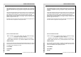
SAFETY INSTRUCTIONS SAFETY INSTRUCTIONS Notice on Safety This equipment is built in accordance with the requirements of the international safety standards EN60950, UL 1950 and CSA C22.2 No.950, which are the safety standards of information technology equipment including electrical business equipment. This equipment is built in accordance with the requirements of the international safety standards EN60950, UL 1950 and CSA C22.2 No.
SAFETY INSTRUCTIONS SAFETY INSTRUCTIONS The lightning flash with an arrowhead within a triangle is intended to tell the user that parts inside this product may cause a risk of electrical shock to persons. The lightning flash with an arrowhead within a triangle is intended to tell the user that parts inside this product may cause a risk of electrical shock to persons.
SAFETY INSTRUCTIONS SAFETY INSTRUCTIONS * All the safety and operating instructions should be read before using this unit. * All the safety and operating instructions should be read before using this unit. * The safety and operating instructions manual should be retained for future reference. * The safety and operating instructions manual should be retained for future reference. * All warnings on the projector and in the documentation manuals should be adhered to.
SAFETY INSTRUCTIONS 3. Do not allow anything to rest on the power cord. Do not locate this product where persons will walk on the cord. To disconnect the cord, pull it out by the plug. Never pull the cord itself. To disconnect the cord, pull it out by the plug. Never pull the cord itself. 4. If an extension cord is used with this product, make sure that the total of the ampere ratings on the products plugged into the extension cord does not exceed the extension cord ampere rating.
SAFETY INSTRUCTIONS SAFETY INSTRUCTIONS c. If the product has been exposed to rain or water. d. If the product does not operate normally when the operating instructions are followed. Note : Adjust only those controls that are covered by the operating instructions since improper adjustment of the other controls may result in damage and will often require extensive work by a qualified technician to restore the product to normal operation. d.
SAFETY INSTRUCTIONS SAFETY INSTRUCTIONS When installing the projector and screen, care must be taken to avoid exposure to ambient light directly on the screen. Avoid adverse illumination on the screen from direct sunlight or fluorescent lighting fixtures. The use of controlled ambient lighting, such as incandescent spot light or a dimmer, is recommended for proper room illumination.
UNPACKING AND DIMENSIONS UNPACKING AND DIMENSIONS UNPACKING 5975069 BARCOVISION 708 MULTIMEDIA 200498 2-1 DIMENSIONS 5975069 BARCOVISION 708 MULTIMEDIA 200498 UNPACKING AND DIMENSIONS UNPACKING AND DIMENSIONS DIMENSIONS UNPACKING 2-1
UNPACKING AND DIMENSIONS UNPACKING AND DIMENSIONS Unpacking To open de banding, pull on the clip as shown in the first drawing. To open de banding, pull on the clip as shown in the first drawing. Take the projector out of its shipping carton and place it on a table. Save the original shipping carton and packing material, they will come in handy if you ever have to ship your projector. For maximum protection, re-pack your projector as it was originally packed at the factory.
UNPACKING AND DIMENSIONS UNPACKING AND DIMENSIONS Projector dimensions 5975069 BARCOVISION 708 MULTIMEDIA 200498 2-3 UNPACKING AND DIMENSIONS UNPACKING AND DIMENSIONS Projector dimensions 5975069 BARCOVISION 708 MULTIMEDIA 200498 2-3
INSTALLATION GUIDELINES INSTALLATION GUIDELINES INSTALLATION GUIDELINES Environment What about ambient light? What about ambient light? Which screen type? Which screen type? What image size? How big should the image be? What image size? How big should the image be? Where to install the projector? How to install the projector? 5975069 BARCOVISION 708 MULTIMEDIA 200498 INSTALLATION GUIDELINES Environment 3-1 Where to install the projector? How to install the projector? 5975069 BARCOVISION 708 M
INSTALLATION GUIDELINES INSTALLATION GUIDELINES Installation guidelines Installation guidelines Careful consideration of things such as image size, ambient light level, projector placement and type of screen to use are critical to the optimum use of the projection system. Careful consideration of things such as image size, ambient light level, projector placement and type of screen to use are critical to the optimum use of the projection system.
INSTALLATION GUIDELINES INSTALLATION GUIDELINES * Which screen type? * Which screen type? There are two major categories of screens used for projection equipment. Those used for front projected images and those for rear projection applications. There are two major categories of screens used for projection equipment. Those used for front projected images and those for rear projection applications.
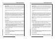
INSTALLATION GUIDELINES INSTALLATION GUIDELINES * Where to install the projector? * Where to install the projector? To indicate a correct installation position it is necessary to know the distance : - projector - ceiling - projector - screen To indicate a correct installation position it is necessary to know the distance : - projector - ceiling - projector - screen To find this correct position for the BARCOVISION 708 MULTIMEDIA, equipped with HD145 lenses, formulas are given in the next paragraph.
INSTALLATION GUIDELINES INSTALLATION GUIDELINES FHLOLQJ FHLOLQJ 3' $ 3' % &' $ SURMHFWRU SURMHFWRU )URQW YLHZ )URQW YLHZ VFUHHQ ZLGWK 6: INSTALLATION GUIDELINES VFUHHQ ZLGWK 6: 7RS YLHZ 5975069 BARCOVISION 708 MULTIMEDIA 200498 &' 3-5 7RS YLHZ 5975069 BARCOVISION 708 MULTIMEDIA 200498 INSTALLATION GUIDELINES % 3-5
INSTALLATION GUIDELINES * How to install the projector? * How to install the projector? Ceiling mount or table mount? To install the projector, apply always the BARCO kits which are specially designed for this function. Ceiling mount or table mount? To install the projector, apply always the BARCO kits which are specially designed for this function. BARCO ceiling support. BARCO ceiling support. Always use the BARCO ceiling support to attach your projector to the ceiling.
INSTALLATION SET UP INSTALLATION SET UP INSTALLATION SET UP INSTALLATION SET UP Access to controls Scan adaptation Scan adaptation 5975069 BARCOVISION 708 MULTIMEDIA 200498 4-1 INSTALLATION SET UP INSTALLATION SET UP Access to controls 5975069 BARCOVISION 708 MULTIMEDIA 200498 4-1
INSTALLATION SET UP INSTALLATION SET UP Access to controls Access to controls Opening procedure : Opening procedure : During the projector set up and installation it is necessary to open the top cover. During the projector set up and installation it is necessary to open the top cover. To gain access, handle as follow : To gain access, proceed as follow : *Turn both lock screws with a screwdriver or a coin counter clockwise. *Turn both lock screws with a screwdriver or a coin counter clockwise.
INSTALLATION SET UP INSTALLATION SET UP During some installations it will become handy to remove the top cover totally. Therefore, - pivot the top cover ± 60° During some installations it will become handy to remove the top cover totally. Therefore, - pivot the top cover ± 60° - push the top cover to the front side of the projector until it jumps out of its hinges. Turn the top cover till 90° and lift it up. - push the top cover to the front side of the projector until it jumps out of its hinges.
INSTALLATION SET UP INSTALLATION SET UP Scan adaptation Scan adaptation The scanning can be switched by turning the Horizontal and Vertical scan connectors and the convergence connectors. To change the scanning, it is necessary to open the projector top cover and to rotate the chassis. For opening the projector's top cover, see Getting access to controls. The scanning can be switch by turning the Horizontal and Vertical scan connectors and the convergence connectors.
INSTALLATION SET UP INSTALLATION SET UP +RUL]RQ WDO VFDQ +RUL]RQ WDO VFDQ FRQQHFWRUV FRQQHFWRUV 9HUWL FDO VFDQ 9HUWL FDO VFDQ FRQQ HFWRUV COMM PORT REMOTE (800 peripherals) R G(S) B S &RQYHUJHQFH FRQQHFWRUV FRQQHFWRUV VIDEO S-VIDEO RS232 IN RS232 OUT COMM PORT REMOTE (800 peripherals) 5975069 BARCOVISION 708 MULTIMEDIA 200498 4-5 R G(S) B S VIDEO S-VIDEO INSTALLATION SET UP INSTALLATION SET UP RS232 IN RS232 OUT FRQQ HFWRUV &RQYHUJHQFH 5975069 BARCOVISION 708 MULTIMEDIA
INSTALLATION SET UP INSTALLATION SET UP A : Horizontal scan inversion A : Horizontal scan inversion Three connectors are used, one for each horizontal deflection coil. When changing the horizontal scan, insure that all three connectors are set in the same position. See position of the connectors for the corresponding projector configuration. Three connectors are used, one for each horizontal deflection coil.
INSTALLATION SET UP INSTALLATION SET UP After scan inversion, close the chassis and close the top cover. Reconnect the power cord to the wall outlet. After scan inversion, close the chassis and close the top cover. Reconnect the power cord to the wall outlet. Note Switching over from floor to ceiling or vice versa requires a complete readjustment of picture geometry and convergence.
INSTALLATION SET UP The 'Projector set up menu' will be displayed. - Select with the control disc 'Identification' and press ENTER. INSTALLATION SET UP The 'Projector set up menu' will be displayed. - Select with the control disc 'Identification' and press ENTER. PROJECTOR SETUP IDENTIFICATION TOTAL RUN TIME CHANGE PASSWORD CHANGE LANGUAGE CHANGE PROJECTOR ADDRESS CHANGE BAUDRATE POWER UP MODE : operating BARCO LOGO Select with or then to return.
PROJECTOR SET UP PROJECTOR SET UP PROJECTOR SET UP PROJECTOR SET UP PROJECTOR SET UP PROJECTOR SET UP Password mode Password mode 5975069 BARCOVISION 708 MULTIMEDIA 200498 5-1 5975069 BARCOVISION 708 MULTIMEDIA 200498 5-1
PROJECTOR SET UP PROJECTOR SET UP Projector Set Up Projector Set Up The strap on the CPU unit allow a set up of the password mode. The strap on the CPU unit allow a set up of the password mode.
PROJECTOR SET UP PROJECTOR SET UP Password mode Password mode With a strap on the controller unit, the important projector adjustments can be protected with a password. When the password feature is enabled (strap mounted on both legs), the customer has to enter a password before he can enter the specific adjustment. With a strap on the controller unit, the important projector adjustments can be protected with a password.
POWER CONNECTION POWER CONNECTION POWER (MAINS) CONNECTION POWER CONNECTION POWER CONNECTION POWER (MAINS) CONNECTION 5975069 BARCOVISION 708 MULTIMEDIA 200498 6-1 5975069 BARCOVISION 708 MULTIMEDIA 200498 6-1
POWER CONNECTION POWER CONNECTION Power (mains) cord connection Power (mains) cord connection Use the supplied power cord to connect your projector to the wall outlet. Plug the female power connector into the male connector at the front of the projector. Use the supplied power cord to connect your projector to the wall outlet. Plug the female power connector into the male connector at the front of the projector.
POWER CONNECTION POWER CONNECTION See installation instructions before connecting to the supply OFF ON - Push out the module. POWER CONNECTION - Push out the module. 5975069 BARCOVISION 708 MULTIMEDIA 200498 V NOM 120/230 Volt I MAX 5/2.5 AMP FREQ 60/50 Hz POWER CONNECTION OFF ON See installation instructions before connecting to the supply V NOM 120/230 Volt I MAX 5/2.
POWER CONNECTION POWER CONNECTION - Loosen both screws of the protective cover and take off the cover. - Loosen both screws of the protective cover and take off the cover. Retaining screws Retaining screws 9 9 - Pull out the 'power selector plug' and re-insert it as illustrated, depending on the wall outlet in the room. - Remount the protective cover and secure with both screws. - Re-insert the module. - Put the plastic cover back and secure both retaining screws.
POWER CONNECTION POWER CONNECTION Switching on/off Switching on/off The projector is switched ON and OFF using the power (mains) switch ON/OFF. The projector is switched ON and OFF using the power (mains) switch ON/OFF. Pressed : ON Not pressed : OFF Pressed : ON Not pressed : OFF The projector can start now in the 'operational mode' (image displayed) or in the 'stand by mode', depending on the position of the 'power up' dip switch on the controller unit.
INSTALLATION ADJUSTMENTS INSTALLATION ADJUSTMENTS INSTALLATION ADJUSTMENTS INSTALLATION ADJUSTMENTS Overview flow chart installation mode Overview flow chart installation mode Scheimpfug adjustment Scheimpfug adjustment Optical lens focusing Optical lens focusing Raster centering 5975069 BARCOVISION 708 MULTIMEDIA 200498 7-1 CRT projection angle adjustment Alignment of the projector 5975069 BARCOVISION 708 MULTIMEDIA 200498 INSTALLATION ADJUSTMENTS Alignment of the projector INSTALLATION AD
INSTALLATION ADJUSTMENTS INSTALLATION ADJUSTMENTS Entering the adjustment mode Entering the adjustment mode ADJUSTMENT MODE ADJUSTMENT MODE Select a path from below : Select a path from below : GUIDED RANDOM ACCESS INSTALLATION SERVICE IRIS Source 1 Select with or then to return. GUIDED RANDOM ACCESS INSTALLATION SERVICE IRIS Source 1 Select with or then to return.
INSTALLATION ADJUSTMENTS INSTALLATION ADJUSTMENTS Overview flow chart installation mode. Overview flow chart installation mode.
INSTALLATION ADJUSTMENTS INSTALLATION ADJUSTMENTS Installation mode start up Installation mode start up It will be necessary to perform several mechanical adjustments while in the installation mode. Remove the top cover in order to gain access to the adjustment points (see Access to controls). Two possible ways to enter the installation mode : It will be necessary to perform several mechanical adjustments while in the installation mode.
INSTALLATION ADJUSTMENTS Push the control disc up or down to highlight "Installation" and press ENTER. INSTALLATION ADJUSTMENTS Push the control disc up or down to highlight "Installation" and press ENTER. ADJUSTMENT MODE Select a path from below : GUIDED RANDOM ACCESS INSTALLATION SERVICE IRIS Source 1 Select with or then to return. GUIDED RANDOM ACCESS INSTALLATION SERVICE IRIS Source 1 Select with or then to return. ENTER continues displaying a WARNING.
INSTALLATION ADJUSTMENTS INSTALLATION ADJUSTMENTS When the password mode is active, your password will be asked. When the password mode is active, your password will be asked. Your password contains 4 digits. Your password contains 4 digits. a) Adjusting the projector with the RCU. a) Adjusting the projector with the RCU. Enter the digits with the numeric keys on the RCU. Enter the digits with the numeric keys on the RCU.
INSTALLATION ADJUSTMENTS INSTALLATION ADJUSTMENTS b) adjusting the projector with the local keypad. b) adjusting the projector with the local keypad. When the 'compose password' menu is displayed, select with the control disc the first digit of your password and press ENTER. Continue by selecting the second digit with the control disc and press ENTER. Handle in the same way for the third and fourth digit.
INSTALLATION ADJUSTMENTS INSTALLATION ADJUSTMENTS Scheimpfug adjustment Scheimpfug adjustment The scheimpfug correction can be adjusted separately for the three tubes within 3 ranges: The scheimpfug correction can be adjusted separately for the three tubes within 3 ranges: range 1 : 1.4 m (55") to 1.9 m (75"), optimum screen width 1.4 m (55") range 2 : 1.9 m (75") to 3.2 m (126"), optimum screen width 2.4 m (94") range 3 : 3.2 m (126") to 6 m (236"), optimum screen width 4 m (157") range 1 : 1.
INSTALLATION ADJUSTMENTS INSTALLATION ADJUSTMENTS 1. Open the top cover (see Gaining access to controls) 1. Open the top cover (see Gaining access to controls) 2. Loosen the lens bolts (do not remove them), and slide the lens to the front until the scheimflug ring can move freely (nutdriver 8 mm or screwdriver). 2. Loosen the lens bolts (do not remove them), and slide the lens to the front until the scheimflug ring can move freely (nutdriver 8 mm or screwdriver).
INSTALLATION ADJUSTMENTS INSTALLATION ADJUSTMENTS Optical lens focusing Optical lens focusing The optical focusing procedure is performed separately for each lens. The appropriate CRT will be switched on as the user proceeds through the optical focusing adjustment sequence. The optical focusing procedure is performed separately for each lens. The appropriate CRT will be switched on as the user proceeds through the optical focusing adjustment sequence. OPTICAL LENS FOCUSING 1.
INSTALLATION ADJUSTMENTS INSTALLATION ADJUSTMENTS Electrical focusing Electrical focusing The electrical focus for red, green and blue is factory preset. When they have to be readjusted, follow the procedure as described below : - Ensure the lenses are correctly focused. - Open the top cover. - Adjust separately the focus control for red, green and blue for the sharpest image on the screen. The electrical focus for red, green and blue is factory preset.
INSTALLATION ADJUSTMENTS INSTALLATION ADJUSTMENTS Raster centering Raster centering The raster must be centered on the CRT screen surface of each tube, therefore, it is necessary to look into the lenses. The raster must be centered on the CRT screen surface of each tube, therefore, it is necessary to look into the lenses.
INSTALLATION ADJUSTMENTS INSTALLATION ADJUSTMENTS FRUUHFW UDVWHU SRVLWLRQ FRUUHFW UDVWHU SRVLWLRQ ZURQJ UDVWHU SRVLWLRQ ZURQJ UDVWHU SRVLWLRQ Press ENTER to activate the raster on the Blue CRT faceplate. Shift the blue raster with the control disc until the raster is centered on the CRT faceplate. Press ENTER to continue with the CRT projection angle adjustment 5975069 BARCOVISION 708 MULTIMEDIA 200498 ENTER continues to CRT Projection angle Adjustment. EXIT returns to Optical focusing.
INSTALLATION ADJUSTMENTS INSTALLATION ADJUSTMENTS CRT projection angle adjustment CRT projection angle adjustment The projection angle of the red and blue CRT's is dependent on the desired size of the projected image. If the centers of green, blue and red do not coincide, the CRT projection angle must be adjusted. Never try to correct this misalignment with the shift correction or the static convergence controls.
INSTALLATION ADJUSTMENTS Projection angle correctly aligned for screen width SW1 INSTALLATION ADJUSTMENTS The same projection angle is misaligned for new screen width SW2. Realignment is necessary. Each screen width change requires readjustment of the projection angle.
INSTALLATION ADJUSTMENTS $ $ Screws A, B, C and D (M4) : upper fixation latch. nutdriver 7mm. Screw A', B', C' and D' (M4) : lower fixation latch. nutdriver 7mm. These screws fasten the cooling house of the red tube. Pivot the red CRT until the center of the red image coincides with the center of the green image. If the angle of the red CRT is corrected, tighten the four bolts. ENTER continues to blue and green crosshairs. %% & & & & '' '' These screws fasten the cooling house of the red tube.
INSTALLATION ADJUSTMENTS These screws fasten the cooling house of the blue tube. Pivot the blue CRT until the center of the blue image coincides with the center of the green image. If the angle of the red CRT is corrected, tighten the four bolts. ENTER continues to the path selection menu. These screws fasten the cooling house of the blue tube. Pivot the blue CRT until the center of the blue image coincides with the center of the green image.
INSTALLATION ADJUSTMENTS Alignment of the projector. Alignment of the projector. Overview of the corrections Overview of the corrections For detailed information about these corrections and procedures to be followed, see owner's manual. (pages given hereafter are for the random access adjustment mode) For detailed information about these corrections and procedures to be followed, see owner's manual.
APPENDIX A : CEILING MOUNT KIT CM50 APPENDIX A : CEILING MOUNT KIT CM50 Ceiling mount kit for 700 projectors (CM50). Ceiling mount kit for 700 projectors (CM50). This ceiling mount with or without pulley system enables to mount the BARCO 700 projector to the ceiling. The concept makes it possible to adapt the projector perfectly to the local mounting requirements in a safe and solid manner.
APPENDIX B : G2 ADJUSTMENT APPENDIX B : G2 ADJUSTMENT G2 adjustment G2 adjustment Enter the adjustment mode by pressing ADJUST and highlight Service. Press ENTER to start up the service mode. ADJUSTMENT MODE Select a path from below : GUIDED RANDOM ACCESS INSTALLATION SERVICE IRIS Source 1 Select with or then to return. GUIDED RANDOM ACCESS INSTALLATION SERVICE IRIS Source 1 Select with or then to return. ENTER starts up the service mode. EXIT returns to operational mode.
APPENDIX B : G2 ADJUSTMENT continue with the G2 adjustment, otherwise press EXIT to return to the service menu. If ENTER is pressed, the G2 menu will be displayed. APPENDIX B : G2 ADJUSTMENT continue with the G2 adjustment, otherwise press EXIT to return to the service menu. If ENTER is pressed, the G2 menu will be displayed.
APPENDIX B : G2 ADJUSTMENT APPENDIX B : G2 ADJUSTMENT - Adjust the G2 potentiometers very slowly with a screwdriver until the corresponding LED just stops illuminating. Repeat the adjust ment for the other colors. - Adjust the G2 potentiometers very slowly with a screwdriver until the corresponding LED just stops illuminating. Repeat the adjust ment for the other colors.