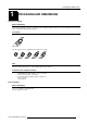
BARCO PROJECTION SYSTEMS REALITY SIM 6 R9040100 - R9040101 R9040110 - R9040111 OWNER'S MANUAL Date : 21032000 Rev. : 00 Art. No.
Federal communication commission (FCC statement) This equipment has been tested and found to comply with the limits for a class B digital device, pursuant to Part 15 of the FCC Rules. These limits are designed to provide reasonable protection against harmful interference when the equipment is operated in a commercial environment.
Table of Contents 1 TABLE OF CONTENTS TABLE OF CONTENTS ...................................................................................................... 1-1 PACKAGING AND DIMENSIONS ...................................................................................... 2-1 Projector Packaging ..................................................................................................................................... 2-1 Way of Packaging .......................................................
Table of Contents Video Input (Optional) ................................................................................................................................... 4-6 S-Video Input (optional) ................................................................................................................................ 4-6 Serial Digital Input / Serial Digital Output (optional) ..................................................................................... 4-7 IEEE 1394 Input ...............
Table of Contents Password Protection ..................................................................................................................................... 6-1 Entering the Password ................................................................................................................................. 6-1 Remark .........................................................................................................................................................
Table of Contents Input Balance ............................................................................................................................................. 7-13 Why adjusting the input balance ? .............................................................................................................. 7-13 How to adjust the input balance ? ..............................................................................................................
Table of Contents Split Screen ............................................................................................................................................... 7-22 Purpose....................................................................................................................................................... 7-22 How to start up ? ........................................................................................................................................
Table of Contents How to enable or disable the password function ? ....................................................................................... 9-4 How to change the password ? .................................................................................................................... 9-4 Change Language ........................................................................................................................................ 9-4 Start Up .....................................
Packaging and Dimensions 1 PACKAGING AND DIMENSIONS Projector Packaging Way of Packaging The projector is packed in a carton box. To provide protection during transportation, the projector is surrounded with foam. the package is the secured with banding and fastening clips. To unpack First release the fastening clips and remove the banding. Handle as shown in the drawing. Pull To open Take the projector out of its shipping carton and place it on a table.
Packaging and Dimensions Projector Case Dimensions The dimensions are given in mm. 25.4 mm = 1" 82.7 211.4 169.5 139.6 14 43 60 42 124.1 124.4 147.8 217.2 46 148.9 380.6 368.7 184.4 526.8 371.2 202.4 53.5 53.5 29.6 1-2 min 12 max 24 97.6 107.5 245.1 120.2 187.2 6 152.6 152.
Installation Guidelines 2 INSTALLATION GUIDELINES Safety warning Before installing the projector, read first the safety instructions Installation Guidelines Ambient Temperature Conditions Careful consideration of things such as image size, ambient light level, projector placement and type of screen to use are critical to the optimum use of the projection system. Max. ambient temperature : 40 °C or 104 °F Min.
Installation Guidelines Projector Configurations Which configuration can be used ? The projector can be installed to project images in four different configurations : Front/table Rear/table Front/ceiling or Rear/ceiling 5HDU &HLOLQJ )URQW &HLOLQJ 5HDU 7DEOH )URQW 7DEOH Positioning the Projector Drawing are given for a nominal lens position. Definitions of the Abbreviation on drawings B = Distance between ceiling and top of the screen or between floor and bottom of the screen.
Installation Guidelines OFF-Axis installation ON-Axis installation CD = B - A Projector SIDE VIEW SIDE VIEW SH CD = B - A Screen SH Projector Screen Optical axis projection lens A’ PD Optical axis projection lens A PD B B CD CD Floor Floor SW SW Screen Screen TOP VIEW TOP VIEW SW SW SH SH Floor BACK VIEW Floor BACK VIEW Lenses Which lens has to be selected. 1 Determine the required screen width.
Installation Guidelines Lens formulas to calculate the projector distance. Metric formulas (meter) Inch formulas (inch) QGD(1.36-2:1) PDmin=1.371 x SW + 0.165 + 0.0083/SW PDmax=2.086 x SW + 0.153 - 0.015/SW PDmin=1.371 x SW + 6.5 + 12.86/SW PDmax=2.086 x SW + 6.02 - 23.25/SW QGD(7:1) PD = 7.021 x SW + 0.047 + 0.0093/SW PD = 7.021 x SW + 1.85 + 14.41/SW QGD(0.8:1) PD = 0.794 x SW - 0.048 + 0.0072/SW PD = 0.794 x SW - 1.89 + 11.16/SW QDG(1.27:1) PD = 1.356 x SW - 0.065 + 0.0297/SW PD = 1.
Installation Guidelines Image 3 Image 4 Cleaning the Lens To minimize the possibility of damaging the optical coating or scratching exposed lens surface, we have developed recommendations for cleaning the lens. FIRST, we recommend you try to remove any material from the lens by blowing it off with clean, dry deionized air. DO NOT use any liquid to clean the lenses. A TorayseeTM cloth is included with the lens kit. Proceed as follows : 1. Always wipe lenses with a CLEAN TorayseeTM cloth. 2.
Installation Guidelines Note Note, only important if more than one projector is installed in the room : 1. the common address can be zero (0) or one (1). The standard RCU are setup for common address zero. To change the common address of the RCU, contact a BARCO service center. If it is necessary to program the projector address into the RCU, see chapter 'Controlling'. 2. projector address has to be reprogrammed everytime the battery is changed, the RCU will always switch to the default address.
Connections 4 CONNECTIONS Power connection to Projector AC Power (mains) cord connection Use the supplied power cord to connect your projector to the wall outlet. Plug the female power connector into the male connector at the front of the projector. The power input is auto-ranging from 90 to 240 VAC. RC TRIG R G B H/C V 1 C OMPUTER M OUSE RS2 32 IN RS23 2 O UT C OMM. PO RT 2 100-240 V 6-2.
Connections To start image projection : a. press the 'Stand by' button once on the local keypad or on the remote control. The projector mode indication lamp will be green. b. press a digit button to select an input source. The projector mode indication lamp will be green.
Connections Switching Off To switch off: - First press STANDBY key for 2 seconds. When the message 'Saving data, please wait' is displayed, do not press any longer on the standby key otherwise the projector will restart. Let cool down the projector at least 10 min. - Switch off the projector with the power switch. Switching to Stand-by Warning When switching to standby, it is possible to restart within the first 5sec.. When not restarted within these first 5 sec., the projector waits for 1 min.
Connections 5-cable Input Slot (slot 1) Slot 1 has 5 BNC input terminals.
Connections Possible indication : RGB [HS&VS] = RGB analog signals, separate sync is horizontal and vertical sync. RGB CS = RGB analog signals, separate sync is composite sync. RGB CV = RGB analog signals, separate sync is composite video or tri-level sync. RGB-SOG = RGB analog signals, sync on green is composite sync. ²COMPONENT VIDEO - CS = separate sync is composite sync. ²COMPONENT VIDEO = component video with composite sync on Y or composite tri-level sync on Y.
Connections How to select Slot 2 Key in 2 on the RCU or the local keypad. Video Input (Optional) What can be connected Composite video signals from a VCR, OFF air signal decoder, etc... 1 x BNC or cinch 1.0Vpp ± 3 dB No loop through. RC 3 VIDEO R G S-VIDEO B 4 SDI H /C SDO IEEE 1394 C OMPU TER 1 V 5 6 TRIG 2 MON ITO R MOU SE R S232 IN C OM M. PO R T R S232 O UT A AUD IO IN AUD IO IN B AUDIO IN C AUD IO IN A, B or C C o m p o site V id e o or or T V tu n e r, e .g .
Connections Pin configuration mini DIN plug 1 2 3 4 ground luminance ground chrominance luminance 1.0Vpp ± 3 dB chrominance 282 mVpp ± 3 dB How to select Slot 4 Key in 4 on the RCU or the local keypad. Serial Digital Input / Serial Digital Output (optional) What can be connected to this input ? Full compatibility with digital Betacam, or digital video sources. This avoids the need for analog processing anywhere in the video production chain and guarantees the ultimate image quality.
Connections RS232 Connection RS232 in / RS232 out To connect a Computer, e.g. IBM PC (or compatible), Apple Macintosh to the RS 232 input of the projector to allow communicate between the computer and the projector. RC 3 VIDEO R G S-VIDEO B 4 H/C SDI SDO V 1 5 IEEE 1394 C OM PUTER 6 TRIG 2 MON ITO R MOU SE R S232 IN AUD IO IN RS232 OUT A AUDIO IN B C OMM.
Connections MOUSE When available ? Mouse function is only available with the Executive Remote Control (Order number : R9829960). The computer can then be controlled via the projector. How to activate ? To activate this mouse function, handle as follow : 1 Start up your computer with the computer mouse plugged in. The mouse driver should be loaded. 2 Unplug the computer mouse without switching off the computer.
Connections 4-10 5976135 BARCOSIM 6 21032000
Getting Started 5 GETTING STARTED Remote Control & Local Keypad How controlling the projector ? The projector can be controlled by the local keypad or by the remote control unit. Location of the local keypad The local keypad is located on the backside of the projector. Remote control This remote control includes a battery powered infrared (IR) transmitter that allows the user to control the projector remotely. This remote control is used for source selection, control, adaptation and set up.
Getting Started 1 Function keys : user programmable keys with functions for direct access. 2 ADJ. : ADJUST key, to enter or exit the adjustment mode. 3 Address key (recessed key), to enter the address of the projector (between 0 and 9). Press the recessed address key with a pencil, followed by pressing one digit button between 0 and 9. 4 Selection key (*) : to direct access the zoom/focus/shift functions. 5 PAUSE : to stop projection for a short time, press 'PAUSE'.
Getting Started Lamp Run Time When the total run time of the lamp is X-30 hours or more, the following warning message will be displayed for 1 minute. This warning message will be repeated every 30 minutes. Press EXIT to remove the message before the minute is over. Remaining Lamp run time 20 h When the total run time of the lamp is X hours or more, the following warning message, with the exact run time is displayed on the screen. Lamp run time is X hours.
Getting Started ZOOM/FOCUS ZOOM with éor ê FOCUS with çor è to Shift to return B. Image shift 1 2 3 4 Press the selection key. The zoom/focus menu will be displayed. Press ENTER. The shift menu will be displayed. Push the cursor key é or ê to shift the image up or down and ç and è to shift the image left and right. When finished, press EXIT key to return or ENTER to continue to zoom/focus.
Getting Started Using the RCU Pointing to the reflective screen Point the front of the RCU to the reflective screen surface. Ceiling Screen IR sensor RCU Hardwired Remote Input. Plug one end of the remote cable in the connector on the bottom of the RCU and the second side in the connector in the front panel of the projector labelled 'RC'. RC 3 V IDE O G R S -VIDE O B 4 SDI 5 SDO H /C COMPUTER 1 V I EE E 13 94 6 TRIG 2 MON ITO R MO USE RS23 2 IN AUDIO IN CO MM.
Getting Started Projector address Why a projector address ? As more than one projector can be installed in a room, the seperate projector should be seperately addressable wiht an RCU or computer. There for each projector has its own address. Set up an Individual Projector Address. The set up of a projector address cab be done via de software. See 'Change projector address' in chapter 'Service mode'. How to control the projector or projectors.
Getting Started Controlling the Projector Input Selection Key in the corresponding slot number with the digit keys on the RCU. The selected source will be displayed. Picture controls. When an image control is pressed, a text box with a bar scale, icon and function name of the control, e.g. 'brightness...' appears on the screen (only if text is ON). See example screen. The length of the bar scale and the value of the numeric indication indicate the current memorized setting for this source.
Getting Started Volume Control Volume control adjusts the volume. Use the + button for a higher volume. Use the - button for a lower volume. Bass Control Bass control adjusts the bass level (low tones). Use the + button for more low tones. Use the - button for less low tones. Treble Control Treble control adjusts the treble level (high tones). Use the + button for more high tones. Use the - button for less hight tones.
Start up of the Adjustment Mode 6 START UP OF THE ADJUSTMENT MODE Adjustment Mode Start Up All source parameters, picture and audio tuning, and geometry are made while in the 'Adjustment Mode'. Press the ADJUST or ENTER key to enter the 'Adjustment mode'. You are now in the 'Adjustment Mode'. 1 2 3 The cursor key (RCU) or '+ or '-' keys (local keypad) are used to make menu selections and also for adjustments. The ENTER and EXIT keys are used to move forward and backward through the menu structure.
Start up of the Adjustment Mode When your password is correct, you gain access to the selected item. When your password is wrong. The error message "Invalid password" is displayed on the screen. Press EXIT to continue and to return to the Service menu. Error Invalid password to return Factory programmed password : 0000 Once the password is correctly entered, all other password protected items are accessible without re-entering the password.
Random Access Adjustment Mode 7 RANDOM ACCESS ADJUSTMENT MODE Random Access Mode Overview Flowchart LOAD EDIT RENAME FILE SERVICE COPY DELETE OPTIONS CTI COLOR TEMPERATURE MOTION COMPENSATION RANDOM ACCESS ADJUSTMENT MODE GAMMA PICTURE TUNING DECODING COLOR DEPTH BLACK COLOR INPUT BALANCE SHIFT SIZE SIDE KEYSTONE GEOMETRY BLANKING ASPECT RATIO OPTIONS VOLUME BALANCE BASS TREBLE AUDIO TUNING MUTE FADE MODE STEREO/MONO VIDEO - AUDIO LOCK TYPE SOFT EDGE SIZE Optional DEMO 5976135 BARCOREALITY SIM6 2
Random Access Adjustment Mode Starting Up Push the cursor key é or ê to highlight 'Random Access' and then press ENTER. ADJUSTMENT MODE Select a path from below : RANDOM ACCESS INSTALLATION SERVICE Source 01 Select with é or ê then to return. Picture Service Connecting a new Source. Before using a new source, a correct file has to be installed. The projector's memory contains a list of files corresponding to the most used sources.
Random Access Adjustment Mode Load File Start up the Load File Push the cursor key é or ê to highlight 'Load' (menu 1). Press ENTER to select. The Load menu displays the corresponding files depending on the installed filter (menu 2). 1 2 This filter can be "Fit" or "All". To change the filter : 1 Push the cursor key è or ç highlight 'filter list'. 2 Press ENTER to toggle the annotation between brackets. "All" : all files that can be loaded will be displayed.
Random Access Adjustment Mode How to start up the Edit menu ? To start up the EDIT menu: 1 Push the cursor key é or ê to highlight 'Edit'. 2 Press ENTER to select. The Edit file adaptation menu will be displayed. 3 Select the file which must be edited (mostly the active file). 4 Press ENTER. The file name will be displayed in the upper right corner. FILE SERVICE LOAD EDIT RENAME COPY Select with é or ê then to return.
Random Access Adjustment Mode If the value for "Horizontal Total Pixels" is wrong, sampling mistakes (small vertical bars in the projected image) will be seen in the image. Select "Total" and adjust the pixel quantity. Adjust for zero bars (hint: if the number of bars increase, adjust in the other direction). The "Active Pixels" : determine the width of the window on the screen. This value is normally given in the source specifications. If not, adjust until full image is displayed (no missing pixels).
Random Access Adjustment Mode Field Polarity : The field polarity function is used for interlaced images. Both rasters of the image could be shifted in a wrong way (double lines are visible in the image). This can be corrected by forcing the field polarity to [neg] or [pos]. Use the ENTER key to toggle between [pos] and [neg]. Field Select : Default [both] The field select is only used for interlaced images. One frame of an interlaced image contains two fields, an even and an odd field.
Random Access Adjustment Mode How to change the characters ? 1 2 3 4 Push the cursor key ç or è to select the desired character. Change that character by pushing the cursor key é or ê. Numeric characters can be entered directly with numeric keys on the RCU. Press ENTER to confirm. The renamed file is entered in the list of files. Press EXIT to return to the Rename menu selection. No changes are made. RENAME FILE Frome file name : Video525.s01 To file name : demo.
Random Access Adjustment Mode Delete Start Up To delete a selected file out of the list of files : 1 Push the cursor key é or ê to highlight 'Delete' (menu 1). 2 Press ENTER. The delete selection menu will be displayed (menu 2). 3 Push the cursor key é or ê to select a file name. 4 Press ENTER to select. If [All] is selected, your password has to be entered before all files will be deleted. A confirmation menu "Delete file 'file name'?" is displayed (menu 3). When you want to delete the file, press ENTER.
Random Access Adjustment Mode Picture Tuning Start Up To improve the image quality, the items in the Picture Tuning menu can be toggled or adjusted. To start up the Picture Tuning : 1 2 Push the cursor key é or ê to highlight 'Picture Tuning' (menu 1). Press ENTER to select. The Picture Tuning menu will be displayed (menu 2). PICTURE TUNING RANDOM ACCESS ADJUSTMENT MODE FILE SERVICE PICTURE TUNING AUDIO TUNNING GEOMETRY SOFT EDGE DEMO Select with é or ê then to return.
Random Access Adjustment Mode How to start up ? 1 2 Push the cursor key é or ê to highlight 'Motion compensation' (menu 1). Press ENTER to select. The motion compensation menu will be displayed (menu 2). PICTURE TUNING PICTURE TUNING CTI [ON] MOTION COMPENSATION COLOR TEMPERATURE GAMMA DECODING [EBU] COLOR DEPTH INPUT BALANCE BLACK COLOR Select with é or ê then to return. LCD SPEED LCD SPEED R/G LCD SPEED B/G menu 1 Select with é or ê then to return.
Random Access Adjustment Mode To change the response time of the Red LCD panel : 1 Push the cursor key é or ê to highlight 'LCD speed R/G' (menu 1). 2 Press ENTER to select. The image will be displayed with together with an adjustment box (menu 2). PICTURE TUNING LCD SPEED R/G 1.00 LCD SPEED LCD SPEED R/G LCD SPEED B/G menu 2 Select with é or ê then to return. menu 1 Color Temperature Start Up Push the cursor key é or ê to highlight 'Color Temperature'. Press ENTER to select.
Random Access Adjustment Mode Gamma What can be adjusted ? With the gamma correction adjustment, it is possible to accurately set the gamma of the projector image. How to change the gamma value ? 1 2 3 4 Push the cursor key é or ê to highlight 'Gamma' (menu 1). Press ENTER to select. Change the gamma value by pushing the cursor key ç or è until the desired value is reached (menu 2). Press EXIT to return to the Picture Tuning menu. Default value of gamma = 1.
Random Access Adjustment Mode To change the Color depth value : 1 2 3 4 Push the cursor key é or ê to highlight 'Color Depth' (menu 1). Press ENTER to select. Change the value by pushing the cursor key ç or è until the desired dark color saturation is reached (menu 2). Adjustment range : 0 ... 8 Default : 4 Press EXIT to return to the Picture Tuning menu.
Random Access Adjustment Mode Continue with the White Balance : 1 Push the cursor key é or ê to highlight 'White Balance' (menu 2). 2 Press ENTER to select. 3 Adjust the Contrast to a maximum value until the white areas are just white (without green noice) and return one step. 4 Adjust with the cursor key é or ê or ç or è until there is no red or blue noise visible in the white areas.
Random Access Adjustment Mode Mute Purpose To stop the sound reproduction. How to stop sound reproduction ? 1 2 1 [A] Push the cursor key é or ê to highlight 'Mute' (menu 1). Press ENTER to toggle between [on] or [off]. AUDIO TUNING VOLUME BALANCE BASS TREBLE MUTE [OFF] FADE MODE [STEREO] VIDEO - AUDIO LOCK 2 3 4 5 6 [C] [B] [A] [B] [A] Select with é or ê then to return. menu 1 Fade Purpose Determine where the sound signals will be reproduced, internally or externally.
Random Access Adjustment Mode Video - Audio lock Purpose An input source can be locked to an audio input. How to lock input source to an audio source ? 1 2 3 4 5 Push the cursor key é or ê to highlight the first input source (menu 1). Press ENTER to scroll the associated audio input between [A], [B] or [C]. Push the cursor key ç or è to highlight another input source. Press ENTER to scroll between [A], [B] or [C]. Continue for the other inputs in the same way.
Random Access Adjustment Mode Shift What can be done ? The image can be shifted in a horizontal or vertical direction. To start up the shift action : Push the cursor key é or ê to highlight 'Shift' (menu 1). Press ENTER to select. Push the cursor key é or ê to shift the image in a vertical direction. Push the cursor key ç or è to shift the image in a horizontal direction. The default value for the shift is 0.
Random Access Adjustment Mode Side Keystone What can be done ? The side keystone adjustment is used to align the image if the projector is mounted at a nonstandard projection angle. Aligning the keystone 1 2 3 Push the cursor key é or ê to highlight 'Side Keystone' (menu 1). Press ENTER to select. Push the cursor key ç or è to adjust the keystone of the image. When the upper part of the image is wider than the lower part of the image, push the cursor key ç.
Random Access Adjustment Mode Adjusting the blanking. 1 2 3 4 5 Push the cursor key é or ê to highlight 'Blanking' (menu 1). Press ENTER to display the blanking menu. Push the cursor key é or ê to highlight the desired blanking (menu 2) Press ENTER to start up the chosen blanking. Use the cursor keys to adjust the blanking. GEOMETRY BLANKING SHIFT SIZE SIDE KEYSTONE BLANKING ASPECT RATIO [5:4] OPTIONS TOP BOTTOM LEFT RIGHT Select with é or ê then to return.
Random Access Adjustment Mode Options How to change the geometry options ? 1 2 Push the cursor key é or ê to highlight 'Options' (menu 1). Press ENTER to display the Geometry options menu (menu 2). GEOMETRY GEOMETRY OPTIONS SHIFT SIZE SIDE KEYSTONE BLANKING ASPECT RATIO [5:4] OPTIONS Use the same side keystone correction for all files ? [YES] Select with é or ê then to return.
Random Access Adjustment Mode Available soft edge types. None : no soft edge area installed (image 1). Left : soft edge on left side of the image (image 2). Both : soft edge on both sides of the image (image 3). Right : soft edge on right side of the image (image 4). image 1 image 2 image 3 image 4 Size Purpose To change the width of the installed soft area. How to set up the width ? 1 2 Push the cursor key é or ê to highlight 'Size' (menu 1). Press ENTER to select.
Random Access Adjustment Mode Split Screen Purpose To have a demonstration of the image settings such as : sharpness, de-interlacing, color depth and TMR (true motion reproduction). How to start up ? 1 2 Push the cursor key é or ê to highlight 'Split Screen' (menu 1). Press ENTER to toggle between on and off. When on : the screen will split in the middle. One half will stay as the settings are and the other half will change while changing the settings.
Installation Mode 8 INSTALLATION MODE Installation Mode Start Up Push the cursor key é or ê to highlight 'Installation Mode' and then press ENTER. ADJUSTMENT MODE INSTALLATION INPUT SLOTS 800 PERIPHERALS CONFIGURATION OSD COLOR INTERNAL PATTERNS NO SIGNAL LENS MENU POSITION QUICK ACCESS KEYS Select with é or ê then to return. Select a path from below : RANDOM ACCESS INSTALLATION SERVICE Source 01 Select with é or ê then to return.
Installation Mode Possible results for the input slots : Source indication Video or S-Video Video S-Video RGB analog RGB-CV : separate sync is composite video signal on H/C input RGB-HS&VS : separate sync is horizontal and vertical sync RGB-CS : separate sync is composite sync RGB-SOG : sync on green Component video Component Video What if a switcher is connected to the projector ? If a RCVDS (switched on) or VS05 is connected to the projector, it will be also indicated on the menu by adding +800 pe
Installation Mode Configuration What can be done ? The way of physical installation of the projector can be defined to the projector. The following installation configurations are possible : - front/table - front/ceiling - rear/ceiling - rear/table Set up the Correct Configuration 1 2 Push the cursor key é or ê to highlight 'Configuration' (menu 1). Press ENTER to select. The Configuration menu will be displayed. For more information, see Projector configuration in chapter 3 : 'Installation Guidelines'.
Installation Mode How to select an internal pattern ? 1 2 3 4 Push the cursor key é or ê to highlight 'Internal Patterns' (menu 1). Press ENTER to select. The internal pattern menu will be displayed (menu 2). Push the cursor key é or ê to highlight the Internal Patterns. Press ENTER to display the select internal pattern. INSTALLATION INPUT SLOTS 800 PERIPHERALS CONFIGURATION OSD COLOR INTERNAL PATTERNS NO SIGNAL LENS MENU POSITION QUICK ACCESS KEYS Select with é or ê then to return.
Installation Mode Changing the Shutdown Time The shutdown time can be set between 5 min and 60 min. To set up the shutdown time, handle as follow : 1 Push the cursor key é or ê to highlight 'No signal' (menu 1). 2 Press ENTER to select. 3 Push the cursor key é or ê to highlight 'Shutdown time' (menu 2). 4 Push the cursor key é or ê to change the digits or Enter the digits directly with the digits keys on the RCU.
Installation Mode Lens Adjustments What can be done ? All lens adjustments are motorized and can be adjusted with the RCU. The following items can be adjusted: - Zoom/Focus - Shift To adjust all lens functions such as zoom, focus and shift, handle as follow : 1 Push the cursor key é or ê to highlight 'Lens' (menu 1). 2 Press ENTER to select. The Adjustment pattern will be displayed. With the TEXT key it is possible to toggle between the internal adjustment pattern or the connected source.
Installation Mode Menu Position What can be done ? Menu position can be in the 'Edge' mode where some of the menus will be positionded near the corners of the image, or in the 'Center' mode where all menus will be centered on the image. How to change the setting ? 1 2 Push the cursor key é or ê to highlight 'Menu Position' (menu 1).
Installation Mode 8-8 5976135 BARCOREALITY SIM6 21032000
Service Mode 9 SERVICE MODE Service Mode Start Up Push the cursor key é or ê to highlight 'Service' and then press ENTER. Some items in the Service mode are password protected (when the password function is active). Enter the password to continue. All other password protected items are now available if you stay in the adjustment mode. ADJUSTMENT MODE SERVICE SERVICE Select a path from below : IDENTIFICATION CHANGE PASSWORD CHANGE LANGUAGE CHANGE PROJ.
Service Mode SERVICE PANEL ADJUSTMENT PRESET INPUT BALANCE UNIFORMITY IDENTIFICATION CHANGE PASSWORD CHANGE LANGUAGE CHANGE PROJ. ADDRESS CHANGE BAUDRATE PC RESET LAMP RUNTIME LAMP RUNTINE HISTORY DIMMING MORE... Select the color temperature WHITE BALANCE BLACK BALANCE PROJECTOR WHITE 6500 DEFAULT ADJUST GRAY ADJUST WHITE ADJUST BLACK PURITY DEFAULT INITIALIZE B/W Select with é or ê then press ENTER Select with é or ê then to return.
Service Mode Start Up 1 2 Push the cursor key é or ê to highlight 'Title Page' (menu 1). Press Enter to select. The Title page will be displayed. BARCO REALITY SIM6 IDENTIFICATION TITLE PAGE SIM OPTIONS Proj. address : 001 Soft. version : 1.0 Config : front/ ceiling Baudrate PC : 9600 text : ON Serial no.: 1010200 Run time : 100 h Select with é or ê then to return. menu 1 Select with é or ê then to return.
Service Mode Change Password How to enable or disable the password function ? This item is password protected when the password strap is installed. The password function is enabled when the password strap on the controller module is installed. Consult an authorised Barco service technician to change the strap position. How to change the password ? 1 2 3 Push the cursor key é or ê to highlight 'Change password' (menu 1). Press ENTER to display the Change Password menu (menu 2).
Service Mode Start up 1 2 Push the cursor key é or ê to highlight 'Change Projector Address'' (menu 1). Press ENTER to select. The Change Projector Address menu will be displayed. SERVICE IDENTIFICATION CHANGE PASSWORD CHANGE LANGUAGE CHANGE PROJ. ADDRESS CHANGE BAUDRATE PC RESET LAMP RUNTIME LAMP RUNTINE HISTORY DIMMING MORE ... Select with é or ê then to return. CHANGE PROJ.
Service Mode Change Baudrate PC Start Up 1 2 3 4 Push the cursor key é or ê to highlight 'Change Baudrate PC'' (menu 1). Press ENTER to display the Change Baudrate PC menu. The actual baudrate will be highlighed. The following baud rates are available : 230400/115200/57600/38400/19200/9600/4800/1200 Push the cursor key é or ê to highlight the desired baudrate. Press ENTER to select. SERVICE CHANGE BAUDRATE PC IDENTIFICATION CHANGE PASSWORD CHANGE LANGUAGE CHANGE PROJ.
Service Mode Start Up 1 2 3 Push the cursor key é or ê to highlight 'Lamp Run Time History' (menu 1). Press ENTER to display the Lamp Run Time overview (menu 2). A listing with the lamp serial number and the corresponding run time will be displayed. The actual installed lamp will be marked. Press EXIT to return to the service mode selection menu. SERVICE IDENTIFICATION CHANGE PASSWORD CHANGE LANGUAGE CHANGE PROJ. ADDRESS CHANGE BAUDRATE PC RESET LAMP RUNTIME LAMP RUNTIME HISTORY DIMMING MORE...
Service Mode Motorized Dimming Optional Start Up 1 2 3 4 Push the cursor key é or ê to highlight 'Motorized Dimming' (menu 1). Press ENTER to start up the motorized dimming. Use the cursor keys to change the dimming factor or Press ENTER and type in a dimming factor with the digit keys on the RCU and press ENTER again. Range 3..100 Default : 100 DIMMING LAMP DIMMING MOTORIZED DIMMING Select with é or ê then to return.
Service Mode Panel Adjustments Warning Changing these settings may seriously affect the performance of the projector. All panel adjustments are factory adjusted. If not really necessary, do not touch any of these adjustments. They are useful when a new panel is installed. Start Up 1 2 Push the cursor key é or ê to highlight 'Panel Adjustments'' (menu 1). Press ENTER to select. The following warning will be displayed : Panel Adjustments is reserved to qualified service personnel.
Service Mode Preset Input Balance Warning Changing these settings may seriously affect the performance of the projector. Start Up 1 2 Push the cursor key é or ê to highlight "Preset Input Balance'' (menu 1). Press ENTER to select. The following warning will be displayed : Preset Input Balance is reserved to qualified service personnel. If you are not qualified, press EXIT to cancel the preset input balance.
Appendix A : Standard Source Set Up Files A STANDARD SOURCE SET UP FILES name resolution Fvert Hz 1600_48V 1600 X 600i 1600_60V Fhor kHz pact ltot lact 48,040 62,500 135,000 2160 1600 651 600 1600 X 1200 60,000 75,000 162,000 2160 1600 1250 1200 1600_65V 1600 X 1200 65,000 81,250 175,500 2160 1600 1250 1200 1600_70V 1600 X 1200 70,000 87,500 189,000 2160 1600 1250 1200 8514_a 1024 x 384i 43,479 35,522 44,900 1264 1024 409 384 FHOR kHz : horizontal frequency of the sou
Appendix A : Standard Source Set Up Files A-2 name resolution Fvert Hz mxga_70 1152 x 864 mxga_75 Fhor kHz Fpix MHz ptot pact ltot lact 70,012 63,851 94,500 1480 1152 912 864 1152 x 864 75,000 67,500 108,000 1600 1152 900 864 mxga_80 1152 x 864 80,000 76,640 110,362 1440 1152 958 864 mxga_85 1152 x 864 84,999 77,094 121,500 1576 1152 907 864 mxga_100 1152 x 864 100,000 93,000 145,824 1568 1152 930 864 Video525(*) 1302 x 239i 29,970 15,734 32,207 1302 1024 263 23
Appendix A : Standard Source Set Up Files name resolution Fvert Hz vga_100 640 x 480 vga_gr pact ltot lact 100,000 52,500 44,520 848 640 525 480 640 x 480 59,941 31,469 25,175 800 640 525 480 vga_txt 720 x 400 70,087 31,469 28,322 900 720 449 400 vga75iso 640 x 480 75,000 39,375 31,500 800 640 525 480 xga_60 1024 x 768 60,000 48,360 64,996 1344 1024 806 768 xga_70 1024 x 768 70,000 57,050 78,044 1368 1024 815 768 xga_70v 1024 x 768 69,705 56,182 74,610 1328 1024
Appendix A : Standard Source Set Up Files A-4 5976135 BARCOREALITY SIM6 21032000
Source Numbers 80 - 89 and 90 - 99 B SOURCE NUMBERS 81 - 86 AND 91 - 96 Projector without any 800 peripheral connected. The source numbers 81 - 86 and 91 - 96 do not correspond to physical inputs. An additional adjustment file can be created for these source numbers. This file can contain different settings. The relationship between sources 1 - 6 and 91 - 96 or between 1 - 6 and 81 - 86 is shown in the diagram below.
Source Numbers 80 - 89 and 90 - 99 Source numbers 81 - 86 Only valid if no input module is connected to slot 81 - 86 of a RCVDS05. The source numbers 81 - 86 correspond to the physical inputs 1 - 6 of the projector. e.g. When slot 1 of the projector has to be selected, key in source number 81. The relationship between the sources of slot 1 - 6 of the projector with 800 peripheral is shown in the table below.