
user manual

130 DX-700 • User’s Guide • Rev 02
4. Operation
Using the Display Management Menu
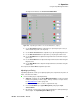
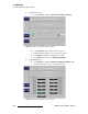
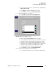
The figure below illustrates the Wall Test Pattern Menu.
Figure 4-66. Wall Test Pattern Menu
b. To set status, enable or disable the Show Internal Test Pattern check
box, as required.
c. To set the pattern color, enable or disable the Red, Green and/or Blue
check boxes.
d. Press {Previous} to return to the Output Display Menu.
This completes the
LED management procedure.
j~å~ÖáåÖ=cáÄÉêäáåâ=pÉííáåÖë
The following procedure applies to Barco “legacy” tiles, such as the MiPIX and the OLite
Series. For these tiles, Fiberlink management functions enable you to view Fiberlink
module properties, set LED wall power, and control test pattern generation through the
Fiberlink NNI Multi-mode Transmitter and Receiver.
This section does not apply to Barco’s NNI-based LED tiles, such as the NX-4 and NX-6,
when using the
Fiberlink NNI Transmitter and Receiver. For more information about the
Fiberlink Transmitter and Receiver modules, refer to Appendix D, “
Fiberlink NNI
Installation” on page 205.
Note
If a wall’s “internal” test pattern is enabled, it overrides all
other video, including video inputs, input test patterns and
Fiberlink test patterns.