
user manual


DX-700 • User’s Guide • Rev 02 41
2. Hardware Orientation
DX-700 Rear Panel
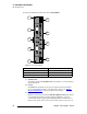
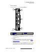
3) Power Supply
The Power Supply connects the DX-700 to your facility’s AC power source. The
integral switch turns the unit on and off. Twin fans are provided for cooling. In
Appendix A, refer to the “
Physical and Electrical Specifications” section on
page 176 for power details.
fåéìí=jçÇìäÉ
The following topics are discussed in this section:
• Input Module Block Diagram
• Input Module Description
fåéìí=jçÇìäÉ=_äçÅâ=aá~Öê~ã
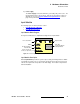
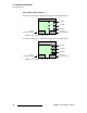
The figure below illustrates a simplified block diagram of the Input Module:
Figure 2-2. Block Diagram - Input Module
fåéìí=jçÇìäÉ=aÉëÅêáéíáçå
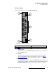
DX-700 Input Modules provide the system’s input, scaling, and mixing functions. Within
each module, the input source is selected from among the various input connectors and
scaled to the required size and position in the final display. The module is fully shielded
and field-installable.
DVI or Dual DVI In
RGB In
Input Module
SD-SDI, HD-SDI, or
Dual HD-SDI In
Bus
Connections
YUV In (Composite,
S-Video, Component)
Expansion Out
Video Out
to next Input Module
or Output Module