
user manual


DX-700 • User’s Guide • Rev 02 91
4. Operation
Using the Setup Wizard
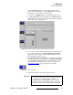
Press the {Horizontal} value box, and use the keypad to enter the
number of horizontal outputs. Press the
{Vertical} value box, and use
the keypad to enter the number of vertical outputs.
If required, press
{Display Reset} to reset the H and V values to 1 x 1.
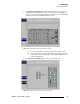
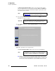
c. Press {Accept Position} to display a graphic in the Output Selection
Section
that represents your selected H and V arrangement. Each gray
square represents an output position.
Figure 4-20. Display Layout Menu: Output Position Arrangement (sample)
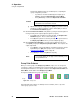
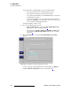
d. To associate each logical output position with a physical DX-700 output,
press a gray “output” square. The
Display Output Selection Menu
appears, with a representation of the rear panel, and buttons for each
physical output that you have set up.
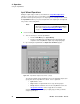
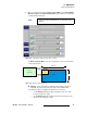
e. On the Display Output Selection Menu, press the button for the output
you want to associate. The system returns to the
Display Layout Menu,
and in the
Output Selection Section, the assignment appears on the
selected button — along with the group’s unique color. Refer to the
“
Group Color Scheme” section on page 92 for color details.
Figure 4-21. Output Assignment
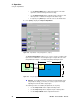
f. Repeat steps d and e for all remaining outputs, if desired.
Important
At least one output must be configured as a group (even in a
1 x 1 array), in order to proceed to the next step. However,
you do not have to configure groups for all outputs.
Depending on your wall configurations, you can configure
groups only for those outputs that you wish to combine into
larger arrays, and leave the remaining outputs “ungrouped.”