
Instruction manual


34 ScreenPRO-II • User’s Guide
3. Hardware Installation
Installation
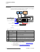
11. Genlock Termination
On the rear of the ScreenPRO-II chassis, one recessed switch is provided for
genlock termination.
a. If you are looping reference video to another chassis in your system, wait
until the system is powered up, then access the
Genlock Menu by
pressing {
HOME} > {OUTPUT} > {GLCK}. This menu enables you to
see the current setting of the termination switch.
b. Press the switch until the “high impedance” (Hi-Z) setting appears.
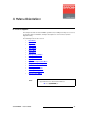
12. System ID — (optional, for use with an Encore or ScreenPRO-II Controller).
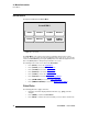
a. Access the Remote Control Menu by pressing {REMOTE CONTROL}
on the
Home Menu. This menu enables you to set the ID of the
ScreenPRO-II chassis.
b. Set the ScreenPRO-II chassis ID to a value that is not used within the
Encore or ScreenPRO-II Controller’s system. The system will not
function properly if duplicate IDs are in use.
13. Display Calibration — calibrate the Touch Screen display using the Display
Settings Menu
. From the Home Menu, press {DISPLAY} > {LCD CAL}, and
following the prompts to calibrate the display.
This completes the hardware installation procedure. Please continue with Chapter 4,
“
Menu Orientation.”
Note
ScreenPRO-II units are shipped from the factory with the
Termination Switch in the “terminated” (75 Ohms) position.
If the ScreenPRO-II chassis is the last device in a reference
video chain, no adjustment to the Termination Switch is
required.
Note
Encore or ScreenPRO-II Controllers will detect multiple IDs
and prompt the user to correct the problem. Only the first
device will connect to the console. Other devices with
conflicting IDs will be refused a connection.