INSTALLATION AND OPERATOR’S MANUAL Manual #26-0208100-00 / Revision E INSTALLATION AND OPERATOR’S MANUAL Model VMS-100 Barco Folsom, LLC 11101 Trade Center Drive Rancho Cordova CA 95670 Phone: (916) 859-2500 • Fax: (916) 859-2515
RECORD OF CHANGES REV # A B DATE 03/18/2003 05/21/2003 ECO # 1001 1059 C D 07/03/2003 10/10/2003 1066 1155 E 8/03/04 1301 DESCRIPTION Release to production. Addition of the storage for Keystone and User-defined warp maps Addition of the Rotation Mode Modify the Capture and Display Menu interface Expanded to cover new features in Maincode release 2.
Operators Safety Summary The general safety information in this summary is for operating personnel. Do Not Remove Covers or Panels There are no user-serviceable parts within the unit. Removal of the top cover will expose dangerous voltages. To avoid personal injury, do not remove the top cover. Do not operate the unit without the cover installed.
ScreenSHAPER Quick Start Guide 1. Identify the following items supplied with the ScreenSHAPER: a. ScreenSHAPER system unit b. ScreenSHAPER AC power cable c. DVI to HD-15 interface adapters (2 supplied) d. RS-232 serial cable, 6 ft. P/N 14-9760048-00 e. CDROM containing Setup and Calibration software and manual 2. Set up an external computer (not supplied) to be used to configure and calibrate the ScreenSHAPER. This computer requires the following: a. Windows 95, 98, 2000, NT or XP operating system b.
Table of Contents SCREENSHAPER ______________________________________________________________________________________I QUICK START GUIDE__________________________________________________________________________________I INTRODUCTION______________________________________________________________________________________ 2 ABOUT THE SCREENSHAPER _____________________________________________________________________________ 2 TYPICAL OPERATION ______________________________________________________________________
Left Edge_____________________________________________________________________________________________ Right Edge ___________________________________________________________________________________________ Top Edge_____________________________________________________________________________________________ Bottom Edge __________________________________________________________________________________________ GAMMA CORRECTION SUBMENU ___________________________________________________________________________
RETURN MATERIAL AUTHORIZATION (RMA) _______________________________________________________________ 42 BARCO FOLSOM CONTACT INFORMATION___________________________________________________________________ 42 TECHNICAL SPECIFICATIONS _______________________________________________________________________ 44 iv ScreenSHAPER – Video Mapping System Manual # 26-0208100-00 / Revision E
1 CHAPTER ONE Introduction What you will find in this chapter… About The ScreenSHAPER Typical Operation Features Model VMS-100 Manual # 26-0208100-00 / Revision E ScreenSHAPER – Video Mapping System 1
Introduction About the ScreenSHAPER The ScreenSHAPER accepts analog RGB video or digital DVI video from one video source and re-maps the image for display on a non-flat or off-axis surface using a projector. The output video is generated in analog and DVI format. An external computer is required to generate the “warp map” used to correct for the non-flat or off-axis surface.
2 CHAPTER TWO Installation What you will find in this chapter… Rear Panel Connectors Rack-Mount Installation Remote Control Connection Video Input & Output Connections Power Cord/Line Voltage Selection Model VMS-100 Manual # 26-0208100-00 / Revision E ScreenSHAPER – Video Mapping System 3
Installation Rear Panel Connectors Figure 2-1: ScreenSHAPER Rear Panel Rack-Mount Installation ScreenSHAPER units are designed to be rack mounted and are supplied with front rack-mount hardware. Rear rackmount brackets are available as a kit and are recommended for use when units are mounted in transit cases. When rack mounting the unit, remember that the maximum ambient operating temperature for the unit is 40 degrees C.
Video In and Video Out Connectors Two DVI-I female connectors are located on the rear panel of the ScreenSHAPER. One is used for VIDEO IN and one is used for VIDEO OUT. Adapters are supplied to connect HD-15 cables to the DVI-I connector for analog devices. Pin Function Pin Function 1 T.M.D.S. Data2- 13 T.M.D.S. Data3+ 2 T.M.D.S. Data2+ 14 +5V Power 3 T.M.D.S. Data2/4 Shield 15 ground (for +5V) 4 T.M.D.S. Data4- 16 Hot Plug Detect 5 T.M.D.S. Data4+ 17 T.M.D.S.
Power Cord/Line Voltage Selection The ScreenSHAPER is rated to operate with the following supplies: Input Power: 98-264VAC, 47-63 Hz Power Consumption: 45 watts maximum The ScreenSHAPER performs line voltage selection automatically. No user controls are required for line voltage selection. WARNING When the ScreenSHAPER is used with 230-volt supplies, a UL listed line cord rated for 250 volts at 15 amps must be used. This cord will be fitted with a tandem prong-type plug.
Connect ScreenSHAPER to AC power using the power cord supplied with the unit. Locate the power switch on the power entry module at the rear of the unit and turn the power on. While the main board is initializing, “please wait” will be displayed and the front panel keys will be turned on and off. When initialization is complete, the Status Display screen will be displayed.
3 CHAPTER THREE Operation What you will find in this chapter… Front Panel Controls System Status Display Menu Control Input Video Setup Menu Output Video Setup Menu Test Pattern Menu System Setup Menu Model VMS-100 Manual # 26-0208100-00 / Revision E ScreenSHAPER – Video Mapping System 9
Operation The ScreenSHAPER must be set up and calibrated using an external computer (not supplied) and the ScreenSHAPER Calibration Software (provided). The front panel can be used to make minor configuration adjustments to the input and output settings. The front panel controls are described in detail in this section; the serial port commands are described in the next section.
System Status Display The System Status Display is displayed whenever a configuration menu is not being displayed. This four-line display contains “SYSTEM STATUS” on the first line indicating that this is the system status display screen. The second line contains the video input format and the input type (ANALOG or DIGITAL). The third line contains the output resolution and frame rate. Depending on the mode of operation, the last line contains the current operation status.
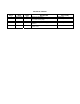
Input Setup Menu This menu is used to configure the input. It is displayed when the IN ADJ key is pressed on the front panel. INPUT SETUP SAVE SETTINGS AUTO CONFIG SYNC SELECT H TOTAL HPOS (PIXELS) VPOS (LINES) CAPTURE AREA PHASE OFFSET BRIGHTNESS CONTRAST RGB COLOR BAL RESET CONFIG ^ ^ AUTO 1688 360 40 N/A 0 100.0% 100.0% >> ^ Save Settings This menu selection is used to save changes made in the Input Setup menu to non-volatile memory.
H Pos V Pos VSync Region Input Active Window V Size Capture Area (Area of Interest) V Start Horizontal Blanking Region (front porch) Horizontal Blanking Region (back porch) HSync Region Vertical Blanking Region (back porch) Vertical Blanking Region (front porch) H Start H Size Figure 3-2 Capture Area Definition H Position This control adjusts the horizontal start of the active video in number of pixels.
H Start H Start is used to set the horizontal start of the capture area in number of pixels. See Figure 3-2 for detail. The default setting is 0. H Size H Size is used to set the horizontal size of the capture area in number of pixels. See Figure 3-2 for detail. The default setting and the maximum setting is the number of active pixels of the input video, based on the input resolution. V Start V Start is used to set the vertical start of the capture area in number of lines. See Figure 3-2 for detail.
Contrast and Brightness Adjustments The Contrast and Brightness controls allow the operator to adjust the overall contrast and brightness of the image if the input is analog. The adjustment range is 75.0% to 125.0%. 100% is the default setting for both contrast and brightness. Contrast and brightness adjustments are only available when using an analog video input. RGB Color Balance Submenu The RGB Color Balance menu item is used to display a submenu where color balance adjustments are performed.
Output Setup Menu The OUTPUT SETUP Menu allows the user to control output image configurations. Based on the Operation Mode, either the Warp Output Setup or the Rotation Output Setup menu is displayed when the OUT ADJ menu key is pressed on the front panel.
H Keystone If the warping function is set to KEYSTONE, this menu selection set the vertical index of the keystone warp. The default is set to 0. Rotation There are four possible rotation angles that can be selected for the output: 0, 90, 180, and 270 degrees. Zero degree corresponds to an un-rotated image and is the default setting. Flip Flip causes the output image to be “mirrored”. Three settings are available: OFF, HORZ, and VERT. HORZ causes the output image to be mirrored left/right.
Display Area Submenu The following four configuration controls, available when operating in the Rotation Mode, are used to set an output display area. The default settings define a full-screen based on the selected output resolution. These settings can be changed to define a particular rectangle within the active output frame. DISPLAY AREA LEFT EDGE RIGHT EDGE TOP EDGE BOTTOM EDGE 0 1280 0 1024 Figure 3-3 Display Area Definition Left Edge Left Edge is used to set the output display area.
Gamma Correction Submenu Gamma Correction can be applied to the individual color components of the output. GAMMA CORRECTION R GAMMA 1.0 G GAMMA 1.0 B GAMMA 1.0 R Gamma The Red Gamma value is applied to the red component of the output. The default setting is 1.0 which is no correction at all. G Gamma The Green Gamma value is applied to the green component of the output. The default setting is 1.0 which is no correction at all. B Gamma The Blue Gamma value is applied to the blue component of the output.
Test Pattern Setup Menu The Test Menu allows the user to select various pre-programmed test patterns to display for positioning and calibrating projectors. This menu is displayed by pressing the TEST PAT key on the front panel. Configuration parameters entered in this menu are saved in non-volatile memory if you issue a SAVE SETTINGS command under the System Setup Menu.
Edge Feather Submenu The Edge Feather Submenu contains the controls to define the edge feather characteristics. EDGE FEATHER LEFT FEATHER LEFT WIDTH LEFT GAMMA RIGHT FEATHER RIGHT WIDTH RIGHT GAMMA CURVE EQUATION DIS 64 1.0 DIS 64 1.0 3rd Left Feather Left Edge Feathering can be Enable/Disable by this control. The default is set to Disable. Left Width The width of the left feathering area is a value between 0 and half the horizontal width of the input. The default is set to 64.
System Setup Menu The System Setup Menu allows the user to control input frame synchronization, change the configuration of the serial port, provides information for access to factory technical support and allows the system to be completely reset to factory default values. This menu is displayed by pressing the SYS SETUP key on the front panel.values.
Stop Bits The number of stop bits can be set to 1 or 2. The default setting is 1 stop bit. Parity Parity can be set to Even, Odd or None. The default setting is NONE. Handshaking Handshaking can be set to On or Off. The default setting is ON. Reset RS-232 All RS-232 parameters can be reset to factory defaults by selecting this menu item and pressing the SEL key. Firmware Versions Menu The Firmware Versions Menu displays the revision information for the system firmware.
DIAGNOSTICS FRONT PANEL TEST I2C TEST >> >> Front Panel Test This selection tests the front panel VFD display, the knob, and the key LEDs. All pixels on the display are tested from top to bottom and then from left to right. The display should illuminate all pixels. The next test will change the display brightness in 16 steps. Then the key LEDs are tested and the user is asked to turn the knob and verify that the displayed position indicator changes correctly.
4 CHAPTER FOUR Remote Commands What you will find in this chapter… ScreenSHAPER Command List/Description Model VMS-100 Manual # 26-0208100-00 / Revision E ScreenSHAPER – Video Mapping System 25
Remote Commands 26 BAUD n Baud Rate: n[0|1|2|3] 1.2K|9.6K|19.2K|38.4K BLKLVL n n n Black Level Mode, Threshold and Offset Intensity: n[0-3] n[0-255] n[0-255] CAP n n n n Capture Input: HStart, HSize, VStart, Vsize COLEN n n Color Enable: n[0|1|2|3] All|Red|Green|Blue CONF Reconfigure Board (FACTORY USE ONLY) CSUM Display Checksum of Files in Flash CURVE n st rd th th th Blend Curve Selection: n[0-4] 1 |3 |5 |7 |9 DBIT n Data Bit: n[7|8] DEBUG password Debug Mode: For internal use only.
INFO System Information Command: FACTORY USE ONLY INFO2 System Information Command: FACTORY USE ONLY IRSP n n Input Raster Size/Position: n[L|R|T|B] n[-999..999] ISYNC n Input Sync.: n[0..3] SOG|CSYN|H&V|AUTO KEY n n Load Keystone warp: n[0-10] n[-8-8], VIndex HIndex LNW Load new warp coefficients LOADR Loader Mode: Place Warper Board into Loader Mode MAP n Load User-defined warp map: n[0-8] OCRECF n Output Resolution: n[0..
ScreenSHAPER Command List/Description Command: BAUD n Description: Set the baud rate for serial command port. Parameters: n [0|1|2|3] 1.2K|9.6K|19.2K|38.4K Query: BAUD ? Returns the current baud rate Example: =n BAUD 3 (Set the baud rate to 38.4K) Command: BLKLVL n n n Description: Set the parameters for black level adjustment on non-blended region of the image. The Adjustment Mode determines how the Threshold and Offset value are applied to the non-blended region of the image.
Command: CONF Description: Parameters: Query: Example: Reconfigure board. Factory use only. None None Conf (The ScreenSHAPER resets using current configuration values.) Command: CSUM Description: Parameters: Query: Example: Display the checksum of the files in flash. For debug use only. None None CSUM (The checksum of the files in flash will be display in the terminal.) Command: CURVE n Description: Select the blend curve algorithm for edge feathering.
Command: ECHO n Description: Turn echo OFF/ON for the serial port. Parameters: n [0|1] OFF/ON Query: ECHO ? Returns the current echo mode Example: =n ECHO 1 (Turn echoing ON) Command: EFTA s en w exp Description: Set the edge feathering parameters. Parameters: s [L|R] Left|Right en [0|1] Disable|Enable w Width of feathering area: [0-640] exp gamma value: [1.0-5.0] Query: EFTA s ? Returns the edge feathering parameters Example: =en w exp EFTA L 1 64 1.
Command: GAM n n n Description: Set the gamma value of the warper chip. Note: This is not the gamma value used for the edge feathering. Default is set to 1.0. Parameters: n Table selection, 1-3, VPC|GPC|DPC n Color selection, 0-3, All|Red|Green|Blue n Gamma Value; 0.0-5.0 Query: GAM ? Returns the current gamma value. GPC/VPC = n.n n.n n.n DPC = n.n n.n n.n Example: GAM 2 0 1.5 (Set the gamma value to 1.5 for all colors on the GPC.) GAM 3 1 1.0 (Set the gamma value to 1.0 for Red on the DPC.
Command: ICPHO op nn Description: Adjusts the Input Clock Phase Offset of the current source. Parameters: op option[A|M] Auto|Manual nn Phase value; [-16…15] Query: ICPHO ? Returns the Input Clock Phase of the current source in the format: =nn Example: ICPHO m 7 (Set the input phase offset to 7.) ICPHO d (Enter the debug mode for adjusting the input phase offset.) Command: ICPL op nnnn Description: Adjusts the Input Clocks Per Line of the current source.
Command: INFO Description: System Information Command. For internal use only Parameters: Example: NONE NONE Command: INFO2 Description: System Information Command. For internal use only Parameters: Example: NONE NONE Command: IRSP Description: Parameters: Example: nn Adjust the input active window. n Edge to adjust, L|R|T|B, Left|Right|Top|Bottom n Offset, [-999..999]. IRSP l 2 (Adjust the left edge 2 pixels to the right.) IRSP B -2 (Adjust the bottom edge 2 lines up.
Command: MAP n Description: Index a user-defined warp map. The warp map has to be loaded prior to turning the warping function ON. It is required that the loaded warp map was generated for the current input-output resolution. This command is only recognized in the WARP Operation Mode. Parameters: nIndex of the user-defined warp map, [0-8] Query: MAP ? Returns the currently selected user-defined warp map. =n Example: KEY 2 (The user-defined warp map [2] is loaded.
Command: ORAS n Description: Puts a white raster box on the output display if Rotation is at 0 degree. If Rotation is at 90, 180 or 270, the output raster box can not be enabled. Note: If the display area is not full screen, the edge area will be white when Output Raster Box is Enabled. Parameters: n[0|1] Disable|Enable Query: ORAS ? Returns the output raster box mode: =n Example: ORAS 1 (Select to put a white raster box on the output display). Command: OSYNC n Description: Adjusts the Output Sync.
Command: SBIT n Description: Set the number of stop bit for serial command port. Parameters: n [1|2] Query: SBIT ? Returns the number of stop bit. Example: =n SBIT 1 (Set the serial port for 1 stop bit) Command: SYNC n Description: Selects the output sync method. Note: External sync input required if non-zero. Parameters: n [0|1|2] Freerun|Line Locked|Frame Locked Query: SYNC ? Returns the current sync mode Example: =n SYNC 2 (Frame lock output timing to external vertical sync.
Command: WARP n Description: Enable/Disable the warp function. If the warp function is set to ON, the warp map used is set by the MAP command. If the warp function is set to KEYSTONE*, the warp mapused is set by the KEY command. This command is only recognized in the WARP Operation Mode.
5 CHAPTER FIVE Software Upgrade Instructions What you will find in this chapter… Software Upgrade Instructions Model VMS-100 38 ScreenSHAPER – Video Mapping System Manual # 26-0208100-00 / Revision E
Software Upgrade Instructions Overview The ScreenSHAPER units incorporate the system software in a Flash memory component. Flash memory allows easy upgrades without the need to send the unit back to the factory due to software or firmware changes. The loader utility provides the capability to update the system Flash module with the latest revision of software. The upgrade utility can be run from a hard drive (recommended) or a floppy drive.
Starting the Flash File Loader Utility After the files have been installed the Flash File Loader can be selected to run. 1. Click on the Start button and select Programs. 2. Find the Folsom Research folder and select Flash File Loader. Preparing to Upgrade the ScreenSHAPER Unit 1. Plug the DB-9 male connector into the port labeled “RS-232” on the back of the ScreenSHAPER unit. 2.
6 CHAPTER SIX Barco Folsom Information What you will find in this chapter… Warranty RMA Information Technical Support/General Contact Information Model VMS-100 Manual # 26-0208100-00 / Revision E ScreenSHAPER – Video Mapping System 41
Barco Folsom Information Barco Folsom, LLC Warranty All video products are designed and tested to the highest quality standards and are backed by a full 3-year parts and labor warranty. Warranties are effective upon delivery date to customer and are non-transferable. Barco Folsom, LLC warranties are only valid to the original purchaser/owner.
A APPENDIX A Technical Specifications Model VMS-100 Manual # 26-0208100-00 / Revision E ScreenSHAPER – Video Mapping System 43
Technical Specifications Video Input Number: 1 Video Signal Format: Analog RGB or Digital DVI Resolution: SVGA (800x600) to SXGA (1280x1024) @60 Hz Non-Interlaced Input Sync Signals: Sync-on-Green, Composite Sync, Separate H/V Sync Connectors: One DVI-I Connector supports both analog and digital input. A DVI-I to HD-15 adapter is provided.