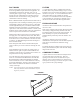
INSTALLATION INSTRUCTIONS WALL MOUNTED PACKAGE AIR CONDITIONERS MODELS W18A1 W18L1 W24A1 W24L1 W30A1 W30L1 W36A1 W36L1 W42A1 W42L1 W48A1 W48L1 W60A1 W60L1 W70A1 W70L1 Bard Manufacturing Company, Inc. Bryan, Ohio 43506 Since 1914...Moving ahead just as planned.
Contents Getting Other Information and Publications Wall Mount General Information Wall Mount Model Nomenclature ............................ Shipping Damage .................................................... General ................................................................ Duct Work ................................................................ Filters ................................................................ Fresh Air Intake .......................................................
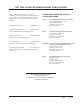
GETTING OTHER INFORMATION AND PUBLICATIONS These publications can help you install the air conditioner or heat pump. You can usually find these at your local library or purchase them directly from the publisher. Be sure to consult current edition of each standard. FOR MORE INFORMATION, CONTACT THESE PUBLISHERS: ACCA Air Conditioning Contractors of America 1712 New Hampshire Ave. N.W.
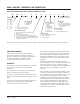
WALL MOUNT GENERAL INFORMATION AIR CONDITIONER WALL MOUNT MODEL NOMENCLATURE W 42 A 1 – A 10 X X X X KW CAPACITY 18 - 1½ Ton 24 - 2 Ton 30 - 2½ Ton 36 - 3 Ton 42 - 3½ Ton 48 - 4 Ton 60 - 5 Ton 70 - 6 Ton VOLTS & PHASE A - 230/208/60/1 B - 230/208/60/3 C - 460/60/3 A - Right Hand Air Conditioner L - Left Hand Air Conditioner VENTILATION OPTIONS X - Barometric Fresh Air Damper (Standard) B - Blank-off Plate M - Motorized Fresh Air Damper V - Commercial Ventilator - Motorized with Exhaust E - Econ
DUCT WORK FILTERS All duct work, supply and return, must be properly sized for the design airflow requirement of the equipment. Air Conditioning Contractors of America (ACCA) is an excellent guide to proper sizing. All duct work or portions thereof not in the conditioned space should be properly insulated in order to both conserve energy and prevent condensation or moisture damage. A 1-inch throwaway filter is standard with each unit. The filter slides into position making it easy to service.
INSTALLATION INSTRUCTIONS WALL MOUNTING INFORMATION 1. Two holes for the supply and return air openings must be cut through the wall as shown in Figure 3. 2. On wood frame walls, the wall construction must be strong and rigid enough to carry the weight of the unit without transmitting any unit vibration. 3. Concrete block walls must be thoroughly inspected to insure that they are capable of carrying the weight of the installed unit.
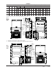
FIGURE 2 Dimensions of Basic Unit for Architectural and I nstallation Requirements (Nominal) MODEL WIDTH DEPTH HEIGHT SUPPLY (W) (D) (H) A B RETURN C B E F G I J K L M N O P Q R S T W18A, L 33.300 17.125 70.563 7.88 19.88 11.88 19.88 35.00 11.00 25.75 20.56 26.75 28.06 29.25 27.00 2.63 34.13 22.06 10.55 4.19 12.00 5.00 W24A, L W30A, L 38.200 17.125 70.563 7.88 27.88 13.88 27.88 40.00 11.00 25.75 17.93 26.75 28.75 29.25 27.00 2.75 39.19 22.75 9.14 4.19 12.00 5.00 W36A, L W42A, L W48A, L 42.075 22.432 84.
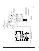
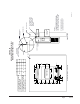
Manual 2100-508A Page 8 of 25 13 3 16 " 5" 12" 12" 12" 12" 12" 4" Typ. 1" 20" 1 1 7 16 " 2" 38" 4" Typ. Return Opening Supply Opening 20" Wall Opening and Hole Location View 2" 7 8" 3" 1 7 16 " 1" 12" 1 20 2 " 8" WALL TOP HEATER ACCESS PANEL SEAL WITH BEAD OF CAULKING ALONG ENTIRE LENGTH OF TOP. FIGURE 3A W18A1, W18L1, W24A1, W24L1 MOUNTING INSTRUCTIONS Right Side View W**A UNIT SHOWN, W**L UNIT CONTROLS AND HEATER ACCESS IS ON OPPOSITE (LEFT) SIDE.
Manual 2100-508A Page 9 of 25 1 E 5" 12" 12" 12" 12" 12" D 1 42" 3" 4" Typ. 1" 28" 3 " 4" 8 Typ. Return Opening Supply Opening A 10 1 42" C Wall Opening and Hole Location View 7 8" C 30 1" 14" E B 4 1/2 4 9/16 16 7/8 D REQUIRED DIMENSIONS TO MAINTAIN RECOMMENDED 1" CLEARANCE FROM COMBUSTIBLE MATERIALS C 5 1/4 3 13/16 17 5/8 B REQUIRED DIMENSIONS TO MAINTAIN 28 1/2 8 1/2 1/4" MIN.
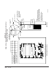
Manual 2100-508A Page 10 of 25 7 18" 16" 16" 16" 16" 16" 1 1 4" Typ. 1 1 62" 38" C 5 1/2 6 1/4 C D 2 E 29 29 3/4 7 8" 28" 1 16" E B 1 1/4 Dimension is 21" on W70A and W70L Units. 4" Typ. 1" 3" 30" Return Opening Supply Opening A 12 10 1/2 B Wall Opening and Hole Location View 1 1 62" 1 62" C 32 REQUIRED DIMENSIONS TO MAINTAIN RECOMMENDED 1" CLEARANCE FROM COMBUSTIBLE MATERIALS D 30 1/2 REQUIRED DIMENSIONS TO MAINTAIN 1/4" MIN.
FIGURE 4 ELECTRIC HEAT CLEARANCE W30A1, W30L1, W36A1, W36L1, W42A1, W42L1, W48A1, W48L1, W60A1, W60L1, W70A1, W70L1 SIDE SECTION VIEW OF SUPPLY AIR DUCT FOR WALL MOUNTED UNIT SHOWING 1/4 INCH CLEARANCE TO COMBUSTIBLE SURFACES. WARNING A minimum of 1/4 inch clearance must be maintained between the supply air duct and combustible materials. This is required for the first 3 feet of ducting. It is important to insure that the 1/4 inch minimum spacing is maintained at all points.
FIGURE 5 WALL MOUNTING INSTRUCTIONS WALL STRUCTURE SEE FIGURE 3 – MOUNTING INSTRUCTIONS FACTORY SUPPLIED RAIN FLASHING. MOUNT ON UNIT BEFORE INSTALLATION SUPPLY AIR OPENING SUPPLY AIR OPENING SUPPLY AIR DUCT RETURN AIR OPENING RETURN AIR OPENING RETURN AIR OPENING BOTTOM MOUNTING BRACKET. MOUNT ON WALL BEFORE INSTALLING UNIT.
FIGURE 7 COMMON WALL MOUNTING INSTALLATIONS SUPPLY DUCT MAY BE LOCATED IN AN ATTIC OR BELOW CEILING RAFTERS AS SHOWN RAIN FLASHING RAFTERS RAIN FLASHING FINISHED CEILING SURFACE SUPPLY AIR DUCT SUPPLY AIR DUCT W/ GRILLE FINISHED CEILING SURFACE RETURN AIR OPENING W/ GRILLE RETURN AIR OPENING W/ GRILLE OUTSIDE WALL RAFTERS OUTSIDE WALL FREE AIR FLOW NO DUCT DUCTED SUPPLY RETURN AT UNIT SUPPLY DUCT MAYBE LOCATED IN AN ATTIC OR BELOW CEILING RAFTERS AS SHOWN RAIN FLASHING RAFTERS SUPPLY DUCT MAY
WIRING – MAIN POWER WIRING – LOW VOLTAGE WIRING Refer to the unit rating plate for wire sizing information and maximum fuse or “HACR” type circuit breaker size. Each outdoor unit is marked with a “Minimum Circuit Ampacity”. This means that the field wiring used must be sized to carry that amount of current. Depending on the installed KW of electric heat, there may be two field power circuits required. If this is the case, the unit serial plate will so indicate.
START UP THESE UNITS REQUIRE R-410A REFRIGERANT AND POLYOL ESTER OIL. REMEMBER: When adding R-410A refrigerant, it must come out of the charging cylinder/tank as a liquid to avoid any fractionation, and to insure optimal system performance. Refer to instructions for the cylinder that is being utilized for proper method of liquid extraction. GENERAL: 1. Use separate service equipment to avoid cross contamination of oil and refrigerants. 2. Use recovery equipment rated for R-410A refrigerant. 3.
START UP (Continued) IMPORTANT INSTALLER NOTE PHASE MONITOR For improved start up performance wash the indoor coil with a dish washing detergent. All units with three phase scroll compressors are equipped with a 3 phase line monitor to prevent compressor damage due to phase reversal. HIGH PRESSURE SWITCH All W**A/W**L wall mounted air conditioner series models are supplied with a remote reset for the high and low pressure switch.
SEQUENCE OF OPERATION Alarm Relay Output COOLING – Circuit R-Y makes at thermostat pulling in compressor contactor, starting the compressor and outdoor motor. The G (indoor motor) circuit is automatically completed on any call for cooling operation or can be energized by manual fan switch on subbase for constant air circulation. On a call for heating, circuit R-W1 make at the thermostat pulling in heat contact for the strip heat and blower operation.
TROUBLESHOOTING FAN BLADE SETTING DIMENSIONS Shown in Figure 8 is the correct fan blade setting for proper air delivery across the outdoor coil. Refer to Table 1 for unit specific dimension. Any service work requiring removal or adjustment in the fan and/or motor area will require that the dimensions below be checked and blade adjusted in or out on the motor shaft accordingly. REFRIGERANT CHARGE The correct system R-410A charge is shown on the unit rating plate.
TABLE 3 COOLING PRESSURE TABLE Air Temperature Entering Outdoor Coil °F Model W18A1/L1 W24A1/L1 W30A1/L1 W36A1/L1 W42A1/L1 W48A1/L1 W60A1/L1 W70A1/L1 R eturn Air Temperature Pressure 75 deg. D B 62 deg. WB Low S i de High Side 127 295 129 316 131 337 133 360 135 383 137 407 138 432 140 457 141 484 143 511 80 deg. D B 67 deg. WB Low S i de High Side 136 303 138 324 140 346 142 369 144 393 146 417 148 443 150 469 151 496 153 524 85 deg. D B 72 deg.
TABLE 4 Electrical Specifications — W**A Series Single Circuit Dual Circuit Rated Volts and Phase No. Field Power Circuits 3 Minimum Circuit Ampacity 1 Maximum External Fuse or Ckt. Brkr.
TABLE 5 Electrical Specifications — W**L Series Single Circuit Dual Circuit Rated Volts and Phase No. Field Power Circuits 3 Minimum Circuit Ampacity 1 Maximum External Fuse or Ckt. Brkr.
TABLE 6 RECOMMENDED AIRFLOW Model Rated C FM * Rated ESP * Recommended Airflow Range Factory Speed Connection W18A, W18L 550 .40 575 - 725 High W24A, W24L 800 .20 700 - 950 High W30A, W30L 1000 .40 930 - 1300 High W36A, W36L 1100 .30 930 - 1350 High W42A, W42L 1400 .30 1600 - 1150 High W48A, W48L 1550 .20 1750 - 1285 High W60A, W60L 1650 .30 1950 - 1375 High W70A, W70L 1800 .20 2000 - 1475 High * Rated CFM and ESP on high speed tap.
TABLE 9 ELECTRIC HEAT Models 240V-1 208V-1 KW Amps B TU H Amps B TU H 4 16.7 13650 14.4 10240 5 20.8 17065 18.1 12800 6 8 33.3 27300 28.8 41.6 34130 36.2 208V-3 Amps B TU H Amps B TU H Amps B TU H 14.4 20500 12.5 15360 7.2 20500 21.7 30600 18.7 23030 10.8 30700 14.4 40950 18.0 51200 25600 12 15 62.5 51250 54.0 38400 18 20 83.2 68260 72.1 460V-3 20475 9 10 240V-3 36.2 51200 31.2 38400 43.3 61430 37.
EHWA03-A05 X X EHWA03-A08 X X EHWA03-A10 X X EHWA03-A15 X X X EHW36A-B06 X EHWA03-B09 X X EHWA37-B15 X X EHWC03A-C06 X X EHWC03A-C09 X X EHWA03A-C15 X X EHWA05-A05 X X EHWA05-A10 X X X X EHWA05-A15 X X X X EHWA05-A20 X X X X EHWA05-B09 X X EHWA05-B15 X X X X EHW05A-B18 X X X X EHWA05A-C09 X X EHWA05A-C15 X X EHWA60-A05 X X X X WMCB-04B X WMCB-05A X X WMCB-05B X X WMCB-06B X WMCB-08A X X WMCB-09A WMCB-09B Manual 2100-508A Pag
Part Number Description W18, W24 W30, W36 W42, W48, W60, W70 TABLE 11 VENT & CONTROL OPTIONS CMC-14 ODT X X X CMC-15 Start Kit (230V 1-Phase) X X X CMC-23 DDC X X CMC-24 DDC CMC-28 LA C X BFAD-2 Barometric Fresh Air Damper - Standard X BOP-2 Blank Off Plate X MFAD-2 Motorized Fresh Air Damper X CRV-2 Commercial Ventilator - Spring Return X EIFM-2B Economizer X ERVF-2A Energy Recovery Ventilator - 230 Volt X BFAD-3 Barometric Fresh Air Damper - Standard X BOP-3