INSTALLATION INSTRUCTIONS WALL MOUNTED PACKAGED AIR CONDITIONER Models: WA302 WA372 Bard Manufacturing Company, Inc. Bryan, Ohio 43506 Since 1914...moving ahead just as planned. © Copyright 2002 Manual No.
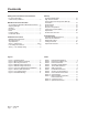
Contents Getting Other Information and Publications For more information, contact these publishers .......................................... 3 Wall Mount General Information Air Conditioner Wall Mount Model Nomenclature .... Shipping Damage .................................................... General .................................................................... Duct Work ................................................................ Filters .........................................................
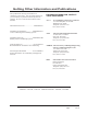
Getting Other Information and Publications These publications can help you install the air conditioner or heat pump. You can usually find these at your local library or purchase them directly from the publisher. Be sure to consult current edition of each standard.
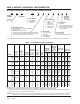
WALL MOUNT GENERAL INFORMATION AIR CONDITIONER WALL MOUNT MODEL NOMENCLATURE WA 37 MODEL NUMBER 2 — A 10 X X X X X KW REVISIONS VOLTS & PHASE A - 230/208/60/1 B - 230/208/60/3 C - 460/60/3 CAPACITY 25 - 2 Ton 37 - 3 Ton VENTILATION OPTIONS X - Barometric Fresh Air Damper (Standard) B - Blank-off Plate M - Motorized Fresh Air Damper V - Commercial Room Ventilator - Motorized with Exhaust E - Economizer (Internal - Fully Modulating with Exhaust R - Energy Recovery Ventilator - with Exhaust COL
Manual Page 2100-404E 5 of 19 FRONT VIEW WA302 38.20 17.125 70.563 WA372 Width Depth Height Model (W) (D) (H) E F G I J K L M N O P Q R S T SIDE VIEW FIGURE 1 UNIT DIMENSIONS BACK VIEW 7.88 27.88 13.88 27.88 40.00 18.50 25.75 17.93 26.75 28.75 29.25 27.00 2.75 39.125 22.75 9.14 4.19 12.00 5.
TABLE 3 ELECTRIC HEAT TABLE WA302-A WA372-A Models 240V-1 WA302-B WA372-B 208V-1 240V-3 WA302-C WA372-C 208V-3 460V-3 KW AMPS B TU H AMPS B TU H AMPS B TU H AMPS B TU H AMPS B TU H 5.0 20.8 17,065 18.1 12,800 --- --- --- --- --- --- 10.0 41.6 34,130 36.2 25,600 --- --- --- --- --- --- 15.0 62.5 51,200 54.1 38,400 --- --- --- --- --- --- 6.0 --- --- --- --- 14.4 20,500 12.5 15,360 7.2 20,475 9.0 --- --- --- --- 21.7 30,600 18.7 23,030 10.
DUCT WORK FRESH AIR INTAKE All duct work, supply and return, must be properly sized for the design airflow requirement of the equipment. Air Conditioning Contractors of America (ACCA) is an excellent guide to proper sizing. All duct work or portions thereof not in the conditioned space should be properly insulated in order to both conserve energy and prevent condensation or moisture damage. All units are built with fresh air inlet slots punched in the service panel.
INSTALLATION INSTRUCTIONS WALL MOUNTING INFORMATION 1. Two holes, for the supply and return air openings, must be cut through the wall as shown in Figure 3. 2. On wood-frame walls, the wall construction must be strong and rigid enough to carry the weight of the unit without transmitting any unit vibration. WARNING Fire hazard can result if 1/4 inch clearance to combustible materials for supply air duct is not maintained. See Figure 3. 3.
The electrical data lists fuse and wire sizes (75ºC copper) for all models, including the most commonly used heater sizes. Also shown are the number of field power circuits required for the various models with heaters. The unit rating plate lists a “Maximum Time Delay Relay Fuse” or “HACR Type” circuit breaker that is to be used with the equipment.
Manual 2100-404E Page 10 of 19 FIGURE 3 MOUNTING INSTRUCTIONS
FIGURE 4 WALL-MOUNTING INSTRUCTIONS SEE FIGURE 3 – MOUNTING INSTRUCTIONS FIGURE 5 WALL-MOUNTING INSTRUCTIONS SEE UNIT DIMENSIONS, FIGURE 1, FOR ACTUAL DIMENSIONS SEE FIGURE 1 FOR DUCT DIMENSIONS Manual Page 2100-404E 11 of 19
FIGURE 6 COMMON WALL-MOUNTING INSTALLATIONS Manual 2100-404E Page 12 of 19
FIGURE 7 ELECTRIC HEAT CLEARANCE Side section view of supply air duct for wall mounted unit showing 1/4 inch clearance to combustible surfaces. WARNING A minimum of 1/4 inch clearance must be maintained between the supply air duct and combustible materials. This is required for the first 3 feet of ducting. It is important to insure that the 1/4 inch minimum spacing is maintained at all points.
FIGURE 8 LOW VOLTAGE WIRING Manual 2100-404E Page 14 of 19
START UP IMPORTANT INSTALLER NOTE PHASE MONITOR For improved start-up performance, wash the indoor coil with a dishwasher detergent. All units with three phase compressors are equipped with a 3 phase line monitor to prevent compressor damage due to phase reversal. HIGH PRESSURE SWITCH The phase monitor in this unit is equipped with two LEDs. If the Y signal is present at the phase monitor and phases are correct the green LED will light.
COMPRESSOR CONTROL MODULE Alarm Relay Output The compressor control module is optional on the models covered by this manual. The compressor control is an anti-short cycle/lockout timer with high and low pressure switch monitoring and alarm relay output. Alarm terminal is output connection for applications where alarm relay is employed. This terminal is powered whenever compressor is locked out due to HPC or LPC sequences as described.
TROUBLESHOOTING FAN BLADE SETTING DIMENSIONS The suction line temperatures in Table 8 are based upon 80ºF dry bulb/67ºF wet bulb (50 percent R.H.) temperature and rated airflow across the evaporator during cooling cycle. Shown in the drawing below are the correct fan blade setting dimensions for proper air delivery across the outdoor coil.
TABLE 12 COOLING PRESSURE Outdoor Temperature °F Model WA302 WA372 Return Air Temperature Pressure 75 80 85 90 95 100 105 110 115 75 deg D B 62 deg WB Low S i de High Side 75 215 76 229 78 244 79 258 80 275 81 292 83 308 84 327 85 345 80 deg D B 67 deg WB Low S i de High Side 80 220 81 235 83 250 85 265 86 282 87 299 89 316 90 335 91 354 85 deg D B 72 deg WB Low S i de High Side 83 228 84 243 86 259 88 274 89 292 90 309 92 327 93 347 94 366 75 deg D B 62 deg W
1 DESCRIPTION WA302-B WA372-B BOP-3 Blank Off Plate X X X X BFAD-3 Barometric Fresh Air Damper X X X X MFAD-3 Motorized Fresh Air Damper X X X X CRV-3 Commercial Ventilator with Exhaust X X X X EIFM-3B Economizer with Exhaust X X X X X X WERV-A3B Energy Recovery Ventilator WERV-A3B Energy Recovery Ventilator CMA-6 Low Ambient Control X X X CMA-16A Low Pressure Control X X X X X WA302-C WA372-C MODEL WA302-A WA372-A TABLE 13 OPTIONAL ACCESSORIES X CMA-