INSTALLATION INSTRUCTIONS WALL MOUNTED PACKAGE HEAT PUMPS Models: CH3S1 CH4S1 CH5S1 NOTE THIS IS AN R-410A HIGH PRESSURE REFRIGERANT SYSTEM Bard Manufacturing Company, Inc. Bryan, Ohio 43506 Since 1914...Moving ahead just as planned.
CONTENTS Getting Other Information and Publications For More Information ............................................... 3 Wall Mount General Heat Pump Wall Mount Model Nomenclature ....... 4 Shipping Damage ................................................. 8 General .............................................................. 8 Duct Work ............................................................. 8 Filters .............................................................. 8 Condensate Drain – Evaporator ..
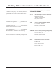
Getting Other Information and Publications These publications can help you install the air conditioner or heat pump. You can usually find these at your local library or purchase them directly from the publisher. Be sure to consult current edition of each standard. FOR MORE INFORMATION, CONTACT THESE PUBLISHERS: ACCA Air Conditioning Contractors of America 1712 New Hampshire Ave. N.W.
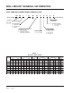
WALL MOUNT GENERAL INFORMATION HEAT PUMP WALL MOUNT MODEL NOMENCLATURE CH 4S 1 – A 05 B P X X X X MODEL NUMBER CONTROL MODULES KW COIL OPTIONS X - Standard CAPACITY REVISIONS 3S - 3 ton 4S - 4 ton 5S - 5 ton VOLTS & PHASE A - 230/208/60/1 B - 230/208/60/3 C - 460/60/3 OUTLET OPTIONS X - Front (Standard) T - Top Outlet VENTILATION OPTIONS B - Blank-off Plate R - Energy Recovery V - Commercial Ventilator Motorized with Exhaust COLOR OPTIONS X - Beige (Standard) 4 - Buckeye Gray 5 - Desert Br
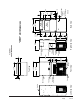
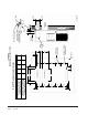
Manual 2100-455A Page 5 of 25 Left Side View Cond. Outlet Grille Slope Top Evap. Drain Hose Vent Option Access Door Filter Access Door Blower Access Door 1 3/8" Heater Access Door 31 5/8" 13 3/8" High Voltage Entrance Low Voltage Entrance C. Breaker Access Door Control Panel Door 84 11/16" 6 7/8" 5 13/16" Drain for optional drain pan Front View Cond.
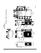
Manual 2100-455A Page 6 of 25 Left Side View Cond. Outlet Grille Slope Top Evap. Drain Hose Vent Option Access Door Filter Access Door Blower Access Door 1 3/8" Front View Heater Access Door 41 5/8" 13 3/8" Access Door High Voltage Entrance Low Voltage Entrance C. Breaker Access Door Control Panel Door 94 11/16" 6 7/8" 5 13/16" Drain for optional drain pan Condenser Inlet Grille 43 7/8" 42 3/16" Top View Optional Top Outlet 39 7/8" Right Side View 22 3/16" Cond.
TABLE 2 ELECTRICAL SPECIFICATIONS SINGLE CIRCUIT DUAL CIRCUIT 1 N o. 3 1 2 2 3 2 2 Maximum Field Minimum Maximum Field Ground Minimum Circuit Field Pow er Ground External Fuse Pow er Circuit External Pow er Wire Ampacity Wire Siz e Wire Siz e or Circuit Ciruits Ampacity Fuse or Wire Siz e Breaker Circuit Siz e Breaker Ckt. Ckt. Ckt. Ckt. Ckt. Ckt. Ckt. Ckt. Ckt. Ckt. Ckt. Ckt.
SHIPPING DAMAGE Upon receipt of equipment, the carton should be checked for external signs of shipping damage. If damage is found, the receiving party must contact the last carrier immediately, preferably in writing, requesting inspection by the carrier’s agent. GENERAL The equipment covered in this manual is to be installed by trained, experienced service and installation technicians. Design the duct work according to methods given by the Air Conditioning Contractors of America (ACCA).
INSTALLATION INSTRUCTIONS WALL MOUNTING INFORMATION 1. Two holes for the supply and return air openings must be cut through the wall as shown in Figure 3. 3. Locate and mark lag bolt locations and bottom mounting bracket location. See Figure 3. 4. Mount bottom mounting bracket. 2. On wood frame walls, the wall construction must be strong and rigid enough to carry the weight of the unit without transmitting any unit vibration. 5. Hook top rain flashing under back bend of top.
18" 3 D 12 32 5 16" 16" 16" 16" 16" 68" C 5 1/2 6 1/2 C 16" 30" Return Opening Supply Opening A 43" 10 30 B 16" 16" 16" 16" C REQUIRED DIM. TO MAINTAIN 0" MIN. CLEARANCE FROM COMBUSTIBLE MATERIALS REQUIRED DIM.
Manual 2100-455A Page 11 of 25 ' & 5HWXUQ 2SHQLQJ 6XSSO\ 2SHQLQJ $ & ( % %RWWRP :DOO %UDFNHW ,QVWDOO EHIRUH XQLW :DOO 5DLQ )ODVKLQJ VXSSOLHG 2SWLRQDO 7RS 2XWOHW 7RS $SSO\ D EHDG RI FDXON DORQJ HQWLUH OHQJWK RI WRS DQG EHKLQG VLGH PRXQWLQJ IODQJHV +HDWHU $FFHVV 3DQHO 8QLW 0RXQWLQJ +ROHV SODFHV ' &+ 6 DQG &+ 6 :DOO 0RXQWLQJ ,QVWUXFWLRQV FIGURE 4 MOUNTING INSTRUCTIONS 5HWXUQ $LU 2SHQLQJ )RDP PLQ
FIGURE 5 ELECTRIC HEAT CLEARANCE Typical Building Outside Sheeting Wall Frame Inside Sheeting Supply Air Duct Unit Supply Air Duct Flange of Wall 1" OPTIONAL CLEARANCE RECOMMENDED Side section view of supply air duct for wall mounted unit showing 0" clearance to combustible surfaces. MIS-2210 Note: This unit is approved for 0" clearance, but the optional 1" clearance is recommended. See Figures 3 & 4.
FIGURE 6 WALL MOUNTING INSTRUCTIONS Interior finished wall Exterior wood or steel siding wall Supply opening Framing material: 2x4's, 2x6's, and/or structural steel Factory supplied rain flashing. Attach to unit before installing. Return opening "CH" Unit Bottom mounting bracket. Mount on wall before installing unit. ! Follow all local building codes when framing wall to support unit.
FIGURE 8 COMMON WALL MOUNTING INSTALLATIONS Free Air Flow - No Duct Low Sound With Acoustical Plenums And Isolation Curbs Free Air Flow - No Duct Unit (outside) Rafters Finished Ceiling Grille Isolation Curb WM1CF5-X ir yA ppl u S Supply Air Free Blow Supply Plenum WAFB51-X Return Air Grille Outside Wall Return Air Silencer WAPR11-X RETURN AIR Ducted Supply - Return At Unit False Wall Installation Note: duct maybe in attic or below rafters as shown.
FIGURE 9 COMMON WALL MOUNTING INSTALLATIONS Closet Installation Note: duct maybe in attic or below rafters as shown. Rafters Unit (outside) WIRING – LOW VOLTAGE WIRING 230 / 208V, 1 phase and 3 phase equipment dual primary voltage transformers. All equipment leaves the factory wired on 240V tap. For 208V operation, reconnect from 240V to 208V tap.
LOW VOLTAGE CONNECTIONS These units use a grounded 24 volt AC low voltage circuit and require at least a 2 stage heating and a 2 stage cooling thermostat. The “R” terminal is the hot terminal and the “C” terminal is grounded. TABLE 4 WALL THERMOSTAT Thermostat Predominant Features 8403-049 (1F93-380) 2 stg. cool; 2 stg. heat Programmable Electronic Auto or Manual changeover “G” terminal is the fan input. “Y” terminal is the compressor Stage 1 input.
START UP CONT’D. SAFETY PRACTICES: The bypass timer should be set to 200 seconds, and this is to assure there is no nuisance tripping of the lowpressure control during startup in heating mode under cold weather conditions. See Figure 10: 1. Never mix R-410A with other refrigerants. 2. Use gloves and safety glasses, Polyol Ester oils can be irritating to the skin, and liquid refrigerant will freeze the skin. FIGURE 11 LOW PRESSURE CONTROL BYPASS TIMER 3.
Verification of proper rotation direction is made by observing that suction pressure drops and discharge pressure rises when the compressor is energized. Reverse rotation also results in an elevated sound level over that with correct rotations, as well as, substantially reduced current draw compared to tabulate values. The direction of rotation of the compressor may be changed by reversing any two line connections to the unit.
DEFROST CYCLE The defrost cycle is controlled by temperature and time on the solid state heat pump control. See Figure 12. When the outdoor temperature is in the lower 40° F temperature range or colder, the outdoor coil temperature is 32° F or below. This coil temperature is sensed by the coil temperature sensor mounted near the bottom of the outdoor coil.
TROUBLESHOOTING SOLID STATE HEAT PUMP CONTROL TROUBLESHOOTING PROCEDURE 1. Turn on AC power supply to indoor and outdoor units. 2. Turn thermostat blower switch to fan on. The indoor blower should start. (If it doesn’t, troubleshoot indoor unit and correct problem.) 3. Turn thermostat blower switch to auto position. Indoor blower should stop. 4. Set system switch to heat or cool. Adjust thermostat to call for heat or cool. The indoor blower, compressor, and outdoor fan should start.
CHECKING TEMPERATURE SENSOR OUTSIDE UNIT CIRCUIT 1. Disconnect temperature sensor from board and from outdoor coil. 2. Use an ohmmeter and measure the resistance of the sensor. Also use ohmmeter to check for short or open. 3. Check resistance reading to chart of resistance use sensor ambient temperature. (Tolerance of part is ± 10%) 4. If sensor resistance reads very low, then sensor is shorted and will not allow proper operation of the heat pump control. 5.
COMPRESSOR SOLENOID A nominal 24-volt direct current coil activates the internal compressor solenoid. The input control circuit voltage must be 18 to 28 volt ac. The coil power requirement is 20 VA. The external electrical connection is made with a molded plug assembly (PN 029-0311-00). This plug contains a full wave rectifier to supply direct current to the unloader coil.
TABLE 7 1 REFRIGERANT CHARGE - SUBCOOLING LEVEL COOLING HEATING Model Rated Airflow 95 OD 80 OD 47 OD 35 OD Temperature Temperature Temperature Temperature CH3S1 1100 16 - 20 15 - 19 28 - 32 26 - 30 CH4S1 1500 18 - 22 17 - 21 20 - 24 15 - 19 CH5S1 1700 26 - 30 20 - 24 31 - 35 27 - 31 1 Expected subcooling levels during high capacity Stage 2 operation. Above subcooling levels are provided to troubleshoot low charge or overcharged conditions.
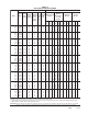
TABLE 10 PRESSURE TABLE HIGH CAPACITY COOLING MODEL RETURN AIR PRESSURE TEMPERATURE CH3S1 CH4S1 CH5S1 7 5 oF 8 0 oF 8 5 oF 9 0 oF 9 5 oF 1 0 0 oF 1 0 5 oF 110oF 115oF 75° D B 62° WB LOW SIDE HIGH SIDE 134 298 134 318 134 339 135 363 137 388 138 415 140 445 143 476 146 510 80° D B 67° WB LOW SIDE HIGH SIDE 143 306 143 326 143 348 144 372 146 398 148 426 150 456 153 488 156 523 85° D B 72° WB LOW SIDE HIGH SIDE 148 317 148 337 148 360 149 385 151 412 153 441 155 472
Manual 2100-455A Page 25 of 25 70° 70° 70° CH3S CH4S CH5S 0 oF 44 290 54 280 44 272 PRESSURE LOW SIDE HIGH SIDE LOW SIDE HIGH SIDE LOW SIDE HIGH SIDE 46 277 55 281 46 295 5 oF 49 284 56 283 50 300 1 0 oF 53 293 56 284 54 303 1 5 oF 57 304 57 288 59 304 2 0 oF 63 316 61 294 64 309 2 5 oF 68 330 66 304 71 318 3 0 oF 75 346 74 317 78 330 3 5 oF 82 364 83 334 86 346 4 0 oF 90 383 94 353 95 364 4 5 oF 99 404 108 376 105 387 5 0 oF AIR TEMPERATURE ENTERING OUTDOOR CO