INSTALLATION INSTRUCTIONS WALL MOUNTED PACKAGE HEAT PUMPS Models: CH3S1 CH4S1 CH5S1 Note This is an R-410A High Pressure Refrigerant System Bard Manufacturing Company, Inc. Bryan, Ohio 43506 Since 1914...Moving ahead just as planned.
Contents Getting Other Information and Publications For More Information................................................. 3 Wall Mount General Heat Pump Wall Mount Model Nomenclature..........4 Shipping Damage....................................................8 General .................................................................8 Duct Work................................................................8 Filters .................................................................
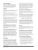
Getting Other Information and Publications These publications can help you install the air conditioner or heat pump. You can usually find these at your local library or purchase them directly from the publisher. Be sure to consult current edition of each standard. For more information, contact these publishers: ACCA Air Conditioning Contractors of America 1712 New Hampshire Ave. N.W.
WALL MOUNT GENERAL INFORMATION HEAT PUMP WALL MOUNT MODEL NOMENCLATURE CH 4S 1 – A 05 B P X X X X MODEL NUMBER CONTROL MODULES KW COIL OPTIONS X - Standard CAPACITY REVISIONS 3S - 3 ton 4S - 4 ton 5S - 5 ton VOLTS & PHASE A - 230/208/60/1 B - 230/208/60/3 C - 460/60/3 OUTLET OPTIONS X - Front (Standard) T - Top Outlet VENTILATION OPTIONS B - Blank-off Plate R - Energy Recovery V - Commercial Ventilator Motorized with Exhaust COLOR OPTIONS X - Beige (Standard) 4 - Buckeye Gray 5 - Deser
Manual 2100-455M Page 5 of 28 Left Side View Cond. Outlet Grille Slope Top Evap. Drain Hose Vent Option Access Door Filter Access Door Blower Access Door 1 3/8" Heater Access Door 31 5/8" 13 3/8" High Voltage Entrance Low Voltage Entrance C. Breaker Access Door Control Panel Door 84 11/16" 6 7/8" 5 13/16" Drain for optional drain pan Front View Cond.
Manual 2100-455M Page 6 of 28 Left Side View Cond. Outlet Grille Slope Top Evap. Drain Hose Vent Option Access Door Filter Access Door Blower Access Door 1 3/8" Front View Heater Access Door 41 5/8" 13 3/8" Access Door High Voltage Entrance Low Voltage Entrance C. Breaker Access Door Control Panel Door 94 11/16" 6 7/8" 5 13/16" Drain for optional drain pan Condenser Inlet Grille 43 7/8" 42 3/16" Top View Optional Top Outlet 39 7/8" Right Side View 22 3/16" Cond.
TABLE 2 ELECTRICAL SPECIFICATIONS SINGLE CIRCUIT DUAL CIRCUIT Rated Volts & Phase No.
SHIPPING DAMAGE Upon receipt of equipment, the carton should be checked for external signs of shipping damage. If damage is found, the receiving party must contact the last carrier immediately, preferably in writing, requesting inspection by the carrier’s agent. GENERAL The equipment covered in this manual is to be installed by trained, experienced service and installation technicians. The refrigerant system is completely assembled and charged. All internal wiring is complete.
INSTALLATION INSTRUCTIONS OPTiOnal top outlet flange Top outlet flange is screwed to the back of the unit upon delivery. Flange must be installed on to the top of the unit before mounting. See Figure 3 for details. MOUNTING THE UNIT 1. These units are secured by wall mounting brackets which secure the unit to the outside wall surface at both sides. 2. The unit itself is suitable for 0 inch clearance. If a combustible wall use a minimum of 30" x 10" supply opening dimensions for sizing.
16" 16" 16" 16" 16" C 16" 30" Return Opening Supply Opening * A 5 1/2 6 1/2 C 16" 16" 16" 16" 12 32 43" 10 30 * NOT USED ON TOP OUTLET UNITS D C REQUIRED DIM. TO MAINTAIN 0" MIN. CLEARANCE FROM COMBUSTIBLE MATERIALS REQUIRED DIM.
Manual 2100-455M Page 11 of 28 16" 16" 16" 16" 16" D C 12 32 43" A 10 B 30 A 30" Return Opening Supply Opening * REQUIRED DIMS. TO MAINTAIN 0" MIN. CLEARANCE FROM COMBUSTIBLE MATERIALS REQUIRED DIMS.
FIGURE 6 ELECTRIC HEAT CLEARANCE Typical Building Outside Sheeting Wall Frame Inside Sheeting Unit Supply Air Duct Flange of Wall Supply Air Duct 1" OPTIONAL CLEARANCE RECOMMENDED Side section view of supply air duct for wall mounted unit showing 0" clearance to combustible surfaces. MIS-2210 Note: This unit is approved for 0" clearance, but the optional 1" clearance is recommended. See Figures 4 & 5.
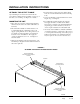
FIGURE 7 WALL MOUNTING INSTRUCTIONS Interior finished wall Exterior wood or steel siding wall Supply opening Framing material: 2x4's, 2x6's, and/or structural steel Factory supplied rain flashing. Attach to unit before installing. Return opening "CH" Unit ! Follow all local building codes when framing wall to support unit. MIS-2024 A FIGURE 8 WALL MOUNTING INSTRUCTIONS 44 7/8" 29 7/8" 3" MIN.
FIGURE 9 COMMON WALL MOUNTING INSTALLATIONS Free Air Flow - No Duct Low Sound With Acoustical Plenums And Isolation Curbs Free Air Flow - No Duct Unit (outside) Rafters Finished Ceiling Grille Isolation Curb WM1CF5-X ir yA ppl u S Supply Air Free Blow Supply Plenum WAFB51-X Return Air Grille Outside Wall Return Air Silencer WAPR11-X RETURN AIR Ducted Supply - Return At Unit False Wall Installation Note: duct maybe in attic or below rafters as shown.
FIGURE 10 COMMON WALL MOUNTING INSTALLATIONS Closet Installation Note: duct maybe in attic or below rafters as shown. Rafters Unit (outside) Duct Supply Air Finished Ceiling WIRING – LOW VOLTAGE WIRING 230 / 208V, 1 phase and 3 phase equipment have 24V transformers with dual primary voltage. All equipment leaves the factory wired on 240V tap. For 208V operation, reconnect from 240V to 208V tap.
low voltage connections These units use a grounded 24 volt AC low voltage circuit and require at least a 2 stage heating and a 2 stage cooling thermostat. “G” terminal is the fan input. “Y” terminal is the compressor Stage 1 input. START UP These units require R-410A refrigerant & Polyol Ester oil. application: 1. Use separate service and manufacturing equipment to avoid cross contamination of oil and refrigerants. “Y1” terminal is the compressor Stage 2 input. 2.
START UP cont’d. safety practices: 1. Never mix R-410A with other refrigerants. 2. Use gloves and safety glasses, Polyol Ester oils can be irritating to the skin, and liquid refrigerant will freeze the skin. 3. Never use air and R-410A to leak check; the mixture may become flammable. 4. Do not inhale R-410A – the vapor attacks the nervous system, creating dizziness, loss of coordination and slurred speech.
PHASE MONITOR All units with three phase compressors are equipped with a 3 phase line monitor to prevent compressor damage due to phase reversal. The phase monitor in this unit is equipped with two LEDs. If the Y signal is present at the phase monitor and phases are correct, the green LED will light. If phases are reversed, the red fault LED will be lit and compressor operation is inhibited. If a fault condition occurs, shut off main power and reverse two of the supply leads to the unit.
DEFROST CYCLE The defrost cycle is controlled by temperature and time on the solid state heat pump control. When the outdoor temperature is in the lower 40°F temperature range or colder, the outdoor coil temperature is 32°F or below. This coil temperature is sensed by the coil temperature sensor mounted near the bottom of the outdoor coil.
There is an initiate defrost jumper (sen jump) on the control that can be used at any outdoor ambient during the heating cycle to simulate a 0° coil temperature. This can be used to check defrost operation of the unit without waiting for the outdoor ambient to fall into the defrost region. By placing a jumper across the SEN JMP terminals (a ¼ inch QC terminal works best) the defrost sensor mounted on the outdoor coil is shunted out & will activate the timing circuit.
TROUBLESHOOTING SOLID STATE HEAT PUMP CONTROL TROUBLESHOOTING PROCEDURE 1. Note: A thorough understanding of the defrost cycle sequence is essential. Review that section earlier in this manual prior to troubleshooting the control. Turn on AC power supply to unit. 2. Turn thermostat blower switch to “fan on” – the indoor blower should start. (If it doesn’t, troubleshoot indoor unit and correct problem.) 3. Turn thermostat blower to “auto” position. Indoor blower should stop.
CHECKING TEMPERATURE SENSOR OUTSIDE UNIT CIRCUIT 1. Disconnect temperature sensor from board and from outdoor coil. 2. Use an ohmmeter and measure the resistance of the sensor. Also use ohmmeter to check for short or open. 3. Check resistance reading to chart of resistance use sensor ambient temperature. (Tolerance of part is ± 10%) 4. If sensor resistance reads very low, then sensor is shorted and will not allow proper operation of the heat pump control. 5.
compressor SOlenoid A nominal 24-volt direct current coil activates the internal compressor solenoid. The input control circuit voltage must be 18 to 28 volt ac. The coil power requirement is 20 VA. The external electrical connection is made with a molded plug assembly (PN 029-0311-00). This plug contains a full wave rectifier to supply direct current to the unloader coil.
TABLE 6 INDOOR BLOWER PERFORMANCE Model Rated ESP j Max ESP CH3S1 .15 0.5 CH4S1 .2 0.5 CH5S1 .2 0.
TABLE 8 PRESSURE TABLE HIGH CAPACITY COOLING MODEL CH3S1 CH4S1 CH5S1 AIR TEMPERATURE ENTERING OUTDOOR COIL DEGREE F RETURN AIR TEMPERATURE PRESSURE 75°F 80°F 85°F 90°F 95°F 100°F 105°F 110°F 115°F 75° DB LOW SIDE 134 134 134 135 137 138 140 143 146 62° WB HIGH SIDE 298 318 339 363 388 415 445 476 510 80° DB LOW SIDE 143 143 143 144 152 148 150 153 156 67° WB HIGH SIDE 306 326 348 372 402 426 456 488 523 85° DB LOW SIDE 148 148 148 149 151 15
Manual 2100-455M Page 26 of 28 70° 70° 70° CH3S CH4S CH5S HIGH SIDE LOW SIDE HIGH SIDE LOW SIDE 44 272 54 280 44 290 LOW SIDE HIGH SIDE 0°F PRESSURE 46 277 55 281 46 295 5°F 49 284 56 283 50 300 10°F 53 293 56 284 54 303 15°F 57 304 57 288 59 304 20°F 63 316 61 294 64 309 25°F 68 330 66 304 71 318 30°F 75 346 74 317 78 330 35°F 82 364 83 334 86 346 40°F 90 383 94 353 95 364 45°F 70° 70° 70° CH3S CH4S CH5S HIGH SIDE LOW SIDE HIGH SIDE LOW SIDE 58 275 60
Troubleshooting GE ECM™ Motors Symptom Caution: Disconnect power from unit before removing or replacing connectors, or servicing motor. To avoid electric shock from the motor’s capacitors, disconnect power and wait at least 5 minutes before opening motor.
Troubleshooting GE ECM™ Motors (Cont'd.) Replacing ECM Control Module To replace the control module for the GE variable-speed indoor blower motor you need to take the following steps: 1. You MUST have the correct replacement module. The controls are factory programmed for specific operating modes. Even though they look alike, different modules may have completely different functionality. Using the wrong control module voids all product warranties and may produce unexpected results. 2.