OIL FURNACE INSTALLATION INSTRUCTIONS MODELS FH085D36D FLF085D36D FLR110D48D FH110D48D FLR085D36D FLR140D60D FH110D60D FLF110D48D FC085D36D WARNING READ ALL INSTRUCTIONS CAREFULLY BEFORE BEGINNING THE INSTALLATION. THIS INSTALLATION MUST COMPLY WITH THESE INSTRUCTIONS AND THE REQUIREMENTS OF ALL GOVERNING CODES AND ORDINANCES FOR THE INSTALLATION LOCATION. IT IS THE RESPONSIBILITY OF INSTALLER TO KNOW AND UNDERSTAND ALL OF THESE REQUIREMENTS.
CONTENTS Getting Other Information and Publications Installation and Operating Instructions Equpment Selection ............................................... 2 Locating the Furnace .............................................. 2 Duct Work ............................................................... 6 Wiring ............................................................... 6 Oil Line Piping ........................................................ 8 Beckett AFG Oil Burner ..................................
GETTING OTHER INFORMATION and PUBLICATIONS These publications can help you install the furnace. You can usually find these at your local library or purchase them directly from the publisher. Be sure to consult current edition of each standard. FOR MORE INFORMATION, CONTACT THESE PUBLISHERS: ACCA Air Conditioning Contractors of America 1712 New Hampshire Ave. N.W.
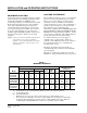
INSTALLATION and OPERATING INSTRUCTIONS EQUIPMENT SELECTION LOCATING THE FURNACE An accurate heating load calculation must be conducted using American Society of Heating, Refrigeration and Air Conditioning Engineers (ASHRAE) or Air Conditioning Contractors of America (ACCA) manuals. Do not add a large safety factor above the calculated value. If the calculated heating load requirement exceeds the heating capacity rating of a given model, use only the next larger size available.
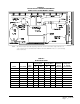
TABLE 2 LO-BOY MODELS DIMENSIONS (INCHES) Plenum Openings Cabinet Model Number A Width B Depth C DxE Height Supply DxF Return G Dia. H Location F LF 085D 36D FLR085D36D 23 23 47-1/4 47-1/4 40-1/4 40-1/4 22x20 22x20 22x16 22x16 Front Rear 6 6 --34 FLR110D48D FLR110D48D 23 23 47-1/4 47-1/4 44-1/4 44-1/4 22x20 22x20 22x16 22x16 Front Rear 6 6 FLR140D60D 26 50 50 25x20 25x16 Rear 6 j Air Filters 1 Flue Connection J Siz e N o.
TABLE 3 HI-BOY MODELS DIMENSION (INCHES) Cabinet Model Number FH085D36D FH110D48D FH110D60D Plenum Openings A Width B Depth C Height DxE Supply FxH 2 Return G Flue Dia. Filter Siz e 23 23 23 31-1/2 31-1/2 31-1/2 56 60 60 22x20 22x20 22x20 23x14 23x14 23x14 6 6 6 16 x 25 16 x 25 20 x 25 j k 1 Washable type filter Left or right side return air option. Must be cut in by installer.
TABLE 4 COUNTERFLOW MODELS DIMENSION (INCHES) Cabinet Plenum Openings Model Number A Width B Depth C Height DxE2 Return FxH Supply G Flue Dia. F C 085D 36D 23 29-1/2 56 22 x 20 18 x 19 6 j k 1 Filter Siz e 10 x 20 15 x 20 Washable type filter Left or right side return air option. Must be cut in by installer.
DUCT WORK The air distribution system should be designed and installed in conformance with manuals published by Air Conditioning Contractors of America (ACCA) as set forth in Manual D, or ASHRAE publications. On replacement installations, particularly if equipment is oversized, the duct systems can easily be undersized.
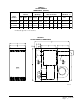
FIGURE 4 TYPICAL INSTALLATION REQUIREMENTS FRONT FLUE LO-BOY MODEL SHOWN MIS-1335 NOTE: The chimney must be lined with a high temperature noncorrosive material that complies with the local codes, or in their absence with Standard for Chimneys and Vents, NFPA211. Also see section on Venting in these instructions. TABLE 5 ELECTRICAL DATA Blow er Motor Burner Motor Max.
OIL LINE PIPING First determine whether the pipe system is to be a single line system or a two line system. All connections must be absolutely air tight or you will have a malfunction of the burner. When installing the piping, a good oil filter should be installed close to the burner. A single line system is recommended for gravity feed. A typical single inside tank installations shown in Figure 5. For installation details for this and other tank configurations, refer to NFPA31 -- latest edition.
The following is a detailed explanation of each control included in the Becket AFG Oil Burner, how each operates, how to set up the burner, and how to troubleshoot problems should they occur. BECKETT “CLEANCUT” OIL PUMP This oil pump is equipped with an oil solenoid valve installed in the pump housing. This feature provides quick cutoffs resulting in reduction in smoke after the burner shuts down. This is a time proven pump design and is capable of both one and two pipe systems.
BECKETT R7184B PRIMARY OPERATIONAL GUIDE Pre-Purge Delay – 15 seconds on delay LED Codes – Flashing 1/2 second on / 1/2 second off – system is locked out or in restricted mode (hard lockout). – Flashing 2 seconds on / 2 seconds off – control is in recycle mode (soft lockout). – ON – CAD cell is sensing flame – OFF – CAD cell is not sensing flame. Ignition Trials – On any given call for heat the control will allow three ignition trials. After the three trials the control will go into a soft lockout mode.
TABLE 6 FURNACE DATA Furnace Installed Standard 2 1 Field Installed Option 2 1 Model Number Noz z le Siz e Input B TU H Heating Capacity B TU H F LF 085D 36D .75 105,000 85,000 .65 91,000 75,000 FLR085D36D .75 105,000 85,000 .65 91,000 75,000 FLF110D48D 1.00 140,000 115,000 .85 119,000 98,000 FLR110D48D 1.00 140,000 115,000 .85 119,000 98,000 FLR140D60D 1.25 175,000 141,000 1.10 154,000 125,000 F C 085D 36D .75 105,000 84,000 .65 91,000 74,000 FH085D36D .
8. Measure the CO2 (or O2) in the flue gas at the trace of smoke level. Open the air control and add reserve air until the CO2 is lowered by 1.5%. Example: Original CO2 at trace of smoke level was 13.0% (3.30% O2). Lower to 11.5% CO2 (5.3% 02). See Table 7. 9. Perform the smoke test again. It should now be at zero. Lock the air settings securely. 10. Measure the stack temperature.
TABLE 7 CORRELATION OF PERCENT OF CO2, O2 AND RESERVE AIR Carbon Dioxide Oxygen Reserve Air (Approx.) 15.4 15.0 14.5 0.0 0.6 1.2 0.0 3.0 6.0 14.0 13.5 13.0 2.0 2.6 3.3 10.0 15.0 20.0 12.5 12.0 11.5 4.0 4.6 5.3 25.0 30.0 35.0 11.0 10.5 10.0 6.0 6.7 7.4 40.0 45.0 50.0 TABLE 8 NO. 2 FUEL OIL EFFICIENCY CHART (NET STACK TEMP. DEGREES F) % O2 200 250 300 350 400 450 500 550 600 650 700 750 800 % O2 1 89.6 88.4 87.3 86.2 85.1 84.0 82.9 81.7 80.6 79.5 78.4 77.3 76.2 14.
BURNER NOZZLE AND ELECTRODE ADJUSTMENTS Check nozzle size as to conformance to installation requirements. Install nozzle by screwing into hexagon adapter. Refer to recommended start-up setting in Table 9. SPACING OF ELECTRODES The electrodes should be spaced 5/32” apart.
APPLIANCES LOCATED IN CONFINED SPACES In unconfined spaces in buildings, infiltration may be adequate to provide air for combustion, ventilation, and dilution of flue gasses. However, in buildings of unusually tight construction, additional air shall be provided using the method described under “All Air From Outdoors” in Figure 8. An unconfined space (such as an open basement) must have a minimum volume of 50 cubic feet per 1,000 BTUH of total of all appliances in area.
TABLE 12 MINIMUM VENTILATION OPENINGS Model Min. Ventilation Opening Square Inch FH085D36D Recommended Opening (2 Required) Siz e Sq. In. 240 8 x 16 128 FH110D48D 280 9 x 18 162 FH110D60D 280 9 x 18 162 F LF 085D 36D 290 8 x 19 152 FLR085D36D 290 8 x 19 152 FLF110D48D 340 9 x 19 171 FLR110D48D 340 9 x 19 171 FLR140D60D 360 9.5 x 19 180 F C 085D 36D 240 8 x 16 128 ALL AIR FROM OUTDOORS A.
FIGURE 10 APPLIANCES LOCATED IN CONFINED SPACES ALL AIR FROM OUTDOORS THROUGH VENTILATED ATTIC NOTE: The inlet and outlet air openings shall each have a free area of not less than one square inch per 4,000 BTU per hour (35 square inches per gallon per hour) of the total input rating of all appliances in the enclosure.
LOUVERS AND GRILLES FAN AND LIMIT CONTROL In calculating free area for above ventilation and combustion air requirements, consideration shall be given to the blocking effect of louvers, grilles, or screens protecting openings. Screens used shall not be smaller than 1/4 inch (6.3 mm) mesh and shall be readily accessible for cleaning. If the free area through a design of louver or grille is known, it shall be used in calculating the size opening required to provide the free area specified.
TABLE 13 TEMPERATURE RISE RANGES, LIMIT CONTROL SETTINGS, AND HEATING BLOWER SPEEDS Rise Ranges Heating Blow er S p eed Limit Setting On Off .65 .75 70 - 100 60 - 90 Low Med 170 170 110 110 90 90 FH110D48D .85 1.00 70 - 100 60 - 90 Low Med Low 170 170 110 110 90 90 FH110D60D .85 1.00 60 - 90 60 - 90 Low Med Low 170 170 110 110 90 90 F LF 085D 36D .65 .75 60 - 90 60 - 90 Low Med 230 230 140 140 110 110 FLF110D48D .85 1.
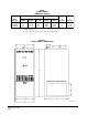
FILTERS All models are shipped with filters. See Table 14 for sizes. See following information. Hi-Boy models are supplied with an external filter rack which can be installed on either left or right side. The counterflow models require a bracket installation and final filter location projects into return air plenum attachment for furnace. See Figure 14. Refer to Figure 14 for Lo-Boy models which have filters internally mounted in blower compartment at rear of furnace.
Figure 13 shows a typical installation of a 20 x 25 x 1 filter rack. The same 14 x 23 cutout is required in the furnace side, and the bottom of the filter rack is aligned over the bottom of the 14 x 23 cutout. The top of the filter rack rises approximately 6 inches above the top of the cutout. The 3 inch depth of the filter rack provides ample spacing between furnace side and leaving edge of filter for the entire filter surface to be effective.
LO-BOY MODELS – FILTER LOCATIONS Lo-boy models have the filter installed in the return air cabinet section of the furnace. It is accessible from the rear of the furnace by removing the blower/filter access door. The electrical switch should be turned “off” prior to removing the access door. Refer to Figure 15 below.
MAINTENANCE INSPECT AIR FILTER Washable air filters are supplied with each furnace. Washable filters should not be replaced with disposable type. Clean filters before each heating season begins. It is recommended that filters also be cleaned at least twice during the heating season. Be sure the new filters are set securely in the filter rack so there can be no leakage around them. (See instructions on inside of blower compartment door.
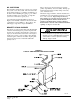
COMBINATION COMBUSTION CHAMBER/BURNER MOUNTING SYSTEM The furnace has been designed with a combustion chamber mounting system that enables service personnel to remove the combustion chamber, its mounting system, and burner assembly as one unit for inspection and/or service on the bench. It has also been designed to remove the burner assembly independently from the mounting system to perform basic annual service and inspection.
TO REMOVE BURNER ONLY Disconnect fuel line, power cord and wires from T, T on primary control. Loosen (3) 1/4 inch nuts securing burner mounting flange. Twist burner counterclockwise and pull straight back away from the furnace. (See Figure 16A.) TO REMOVE THE ENTIRE COMBUSTION CHAMBER MOUNTING SYSTEM Disconnect fuel line, power cord and wires from T, T on primary control. Remove (6) 5/16 inch bolts from around front plate.
COMMON CAUSES OF TROUBLE CAUTION To avoid accidents, always open main switch (OFF position) when servicing the burner. BURNER WILL NOT PRODUCE FLAME Check oil level gauge to see that there is sufficient oil in tank or tanks. Check the burner mounted relay control. Do not adjust this control. Check position of electrodes – incorrect position will cause slow or delayed ignition. Clean electrodes and nozzle. Check and clean strainer in pump. If oil line filter is used, check filter condition.
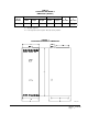
FH RESISTANCE CURVES FH085D36D System Resistance Curves CFM Standard Airflow 1400 1300 HIGH 1200 1100 MED. 1000 900 LOW 800 700 0 0.1 0.2 0.3 0.4 0.5 External Static Pressure in Inches of Water FH110D48D System Resistance Curves 2000 CFM Standard Airflow HIGH 1800 MED.HIGH 1600 1400 MED. LOW 1200 LOW 1000 800 0 0.1 0.2 0.3 0.4 0.
FH RESISTANCE CURVES CFM Standard Airflow FH110D60D System Resistance Curves 2400 2200 HIGH 2000 MED. HIGH 1800 1600 1400 1200 1000 0 0.1 0.2 0.3 0.4 External Stactic Pressure in Inches of Water Manual 2100-392 Page 28 0.
FLF / FLR RESISTANCE CURVES FLF/R085D36D System Resistance Curves CFM Standard Airflow 1500 HIGH 1400 1300 1200 MED. 1100 1000 900 LOW 800 700 0 0.1 0.2 0.3 0.4 0.5 External Static Pressure in Inches of Water FLF/R110D48D System Resistance Curves CFM Standard Airflow 2000 HIGH 1800 MED. HIGH 1600 1400 MED. 1200 1000 800 0 0.1 0.2 0.3 0.4 0.
RESISTANCE CURVES FLR140D60D System Resistance Curves CFM Standard Airflow 2800 HIGH 2600 2400 2200 2000 MED. HIGH 1800 1600 MED. LOW 1400 1200 LOW 1000 0 0.05 0.1 0.15 0.2 0.25 0.3 0.35 0.4 0.45 0.5 External Static Pressure in Inches of Water CFM Standard Airflow FC085D36D System Resistance Curves 1600 HIGH 1400 1200 MED. 1000 LOW 800 600 0 0.1 0.2 0.3 0.4 External Static Pressure in Inches of Water Manual 2100-392 Page 30 0.
Manual 2100-392 Page 31
Manual 2100-392 Page 32
Manual 2100-392 Page 33