OIL FURNACE INSTALLATION INSTRUCTIONS MODELS FH085D36F FLF085D36F FLR085D36F FLR140D60F FH110D48F FLF110D48F FLR110D48F FC085D36F FH110D60F FLF110D60F FLR110D60F WARNING READ ALL INSTRUCTIONS CAREFULLY BEFORE BEGINNING THE INSTALLATION. THIS INSTALLATION MUST COMPLY WITH THESE INSTRUCTIONS AND THE REQUIREMENTS OF ALL GOVERNING CODES AND ORDINANCES FOR THE INSTALLATION LOCATION. IT IS THE RESPONSIBILITY OF INSTALLER TO KNOW AND UNDERSTAND ALL OF THESE REQUIREMENTS.
CONTENTS Getting Other Information and Publications ........ 3 Installation and Operating Instructions Equipment Selection ............................................. 4 Locating the Furnace ............................................ 4 Installing the Furnace ........................................... 8 Duct Work ............................................................. 8 Installing a Cooling Unit ........................................ 8 Wiring ......................................................
GETTING OTHER INFORMATION and PUBLICATIONS These publications can help you install the furnace. You can usually find these at your local library or purchase them directly from the publisher. Be sure to consult current edition of each standard. FOR MORE INFORMATION, CONTACT THESE PUBLISHERS: ACCA Air Conditioning Contractors of America 1712 New Hampshire Ave. N.W.
INSTALLATION and OPERATING INSTRUCTIONS EQUIPMENT SELECTION LOCATING THE FURNACE An accurate heating load calculation must be conducted using American Society of Heating, Refrigeration and Air Conditioning Engineers (ASHRAE) or Air Conditioning Contractors of America (ACCA) manuals. Do not add a large safety factor above the calculated value. If the calculated heating load requirement exceeds the heating capacity rating of a given model, use only the next larger size available.
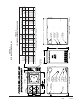
Manual 2100-422M Page 5 of 42 H D F G FILTER DOOR E LEFT SIDE VIEW FRESH AIR KNOCKOUT OPTIONAL OIL ENTRANCE OIL ENTRANCE OPTIONAL LOW VOLTAGE ENTRANCE OPTIONAL HIGH VOLTAGE ENTRANCE "FLF" FLUE KNOCKOUT TOP VIEW REAR FLUE ON "FLR" MODELS RETURN DUCT SUPPLY DUCT J FLF/FLR 085, 110 AND 140 SPECIFICATION SHEET 23 23 23 23 FLF110D 48F FLF110D 60F FLR110D 48F FLR110D 60F "FLF" FLUE KNOCKOUT FRONT VIEW A 26 23 23 FLR140D 60F P lenum Openings 40.625 40.625 40.625 40.
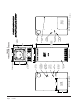
Manual 2100-422M Page 6 of 42 16" LEFT SIDE VIEW RETURN OPENING (CUT OUT) 19 1/4" VESTIBULE DOOR FRESH AIR KNOCKOUT OIL ENTRANCE OPTIONAL OIL ENTRANCE OPTIONAL LOW VOLTAGE ENTRANCE OPTIONAL HIGH VOLTAGE ENTRANCE FLUE KNOCKOUT FLUE KNOCKOUT 19 7/8" TOP VIEW FRONT VIEW 23" 21 7/8" HIGH VOLTAGE ENTRANCE OPTIONAL OIL ENTRANCE LOW VOLTAGE ENTRANCE RIGHT SIDE VIEW RETURN OPENING (CUT OUT) MIS-1814 A FH085 AND FH110 SPECIFICATION SHEET REAR CLEANOUT DOOR FLUE KNOCKOUT 53" (FH085) 59" (FH
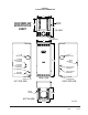
FIGURE 3 FC085 MODEL DIMENSIONS 22" COUNTERFLOW SPECIFICATION SHEET RETURN OPENING 20" 30 5/8" TOP VIEW 23" FLUE KNOCKOUT FLUE KNOCKOUT FLUE KNOCKOUT OPTIONAL HIGH VOLTAGE ENTRANCE 54 1/4" OPTIONAL LOW VOLTAGE ENTRANCE REAR CLEANOUT DOOR LOW VOLTAGE ENTRANCE OIL ENTRANCE HIGH VOLTAGE ENTRANCE OPTIONAL OIL ENTRANCE FRESH AIR KNOCKOUT FRONT VIEW OPTIONAL OIL ENTRANCE LEFT SIDE VIEW RIGHT SIDE VIEW SUPPLY OPENING 18 1/8" BOTTOM VIEW 19 1/8" MIS-1826 A Manual 2100-422M Page 7 of 42
INSTALLING THE FURNACE DUCT WORK INSTRUMENTS REQUIRED FOR PROPER SETUP OF THE FURNACE The air distribution system should be designed and installed in conformance with manuals published by Air Conditioning Contractors of America (ACCA) as set forth in Manual D, or ASHRAE publications. It is important that a set of instruments capable of the following requirements be used for the setup of this furnace to ensure proper and safe operation: 1. Oil pump pressure gauge that measures up to 150 PSI. 2.
FIELD WIRING WIRING All wiring must conform to the National Electrical Code and all local codes. A separate fuse or breaker should be used for the furnace. FACTORY WIRING All units are fully factory wired. Multispeed blowers are factory wired on high speed for cooling/manual fan operation. Heating speeds are wired for the largest input and may need lower speed for field installed low input nozzle. If replacement wire is necessary, use 105 degrees C minimum. See electrical data, Table 3.
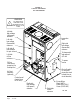
FIGURE 4 TYPICAL UNIT SETUP FLF UNIT SHOWN WARNING ! TYPICAL UNIT SETUP (FLF UNIT SHOWN) ALL WIRING MUST CONFORM TO THE NATIONAL ELECTRIC CODE AND ALL LOCAL CODES. Left side high voltage (unit power) entrance Inspection door Left side low voltage (thermostat) entrance Right side low voltage (thermostat) entrance Left side oil line entrance for opt. air boot To thermostat and optional A/C unit Left side oil line entrance To power source Oil line (see burner pump inst. for hookup info.
FIGURE 5 TYPICAL FLUE INSTALLATION REQUIREMENTS FRONT FLUE LO-BOY MODEL SHOWN (REPRESENTS ALL MODELS) INSTALLER NOTE: Follow all appropriate standards for installing needed venting system. Thimble Draft Regulator (Be sure to follow installation inst. supplied with regulator). 1/4 inch per 1 foot rise L i n e d 90° Rotatable Flue Box on front flue models (remove appropriate cabinet knockout). Mounting screws located under flue box cover.
OIL LINE PIPING BECKETT AFG OR NX OIL BURNER First determine whether the pipe system is to be a single line system or a two line system. All connections must be absolutely air tight or you will have a malfunction of the burner. When installing the piping, a good oil filter should be installed close to the burner. A single line system is recommended for gravity feed.
These controls were selected for their proven high quality, dependability, and serviceability. With proper maintenance this burner assembly will provide many years of reliable service. All units are shipped with the oil burner installed, and with high rate oil nozzle installed designed for use with No. 1 or No. 2 fuel oil. Inspect firepot refractory before firing to be sure it has not been jarred out of position in shipment. Burner air tube must not extend beyond inside surface of firepot.
BECKETT GENISYS MODEL 7505 MIS-2491 PRIMARY OPERATIONAL GUIDE BECKETT GENISYS 7505 Sequence of Operation If the control locks out three times without completing a successful call for heat, the control enters Restricted (Hard) Lockout, and must be reset by a technician. Hold the reset button for 15 seconds until the red light shuts off to reset from Restricted Lockout. 5. Ignition Carryover: Once flame is established, the igniter remains on for 10 additional seconds to ensure flame stability. 6.
TABLE A RESET BUTTON OPERATION Pus hing the Re s e t button will: If the burne r is in the be low s tate : Button Click (pre s s < 1 s e cond) Button Hold (pre s s > 1 s e cond) Lockout Reset from Soft Lockout Valve- on Delay, Trial for Ignition, Ignition Carryover Go to Pump Prime (see Below) Run (igniter is shut off) Yellow LED flashes to indicate cad cell resistance. See "Cad Cell Resistance Indicator" for table of resistance values.
PRIMING THE PUMP WARNING Hot Gas Puff-Back & Heavy Smoke Hazard Failure to bleed the pump properly could result in unstable combustion, hot gas puffback and heavy smoke. • Do not allow oil to spray into a hot combustion chamber while bleeding air from the pump. • Install a gauge in the nozzle discharge port tubing or fully open the pump bleed valve to prevent oil spray from accumulating in the combustion chamber during the air bleed procedure.
RESETTING FROM RESTRICTED LOCKOUT • If the control locks out three times without a satisfied call for heat, or due to other significant events such as a relay contact weld, the Lockout becomes restricted in order to prevent repetitious resetting by the homeowner. CAUTION Before resetting the control from restricted lockout state, troubleshoot the heating system for the root cause(s) of lockout and make necessary repairs or adjustment to ensure a safe start condition.
FIGURE 7 ELECTRONIC BLOWER CONTROL THERMOSTAT CONNECTIONS TRANSFORMER 24V SECONDARY CONNECTIONS 3 AMP FUSE HEATING BLOWER OFF DELAY ADJUSTMENT IN SECONDS.
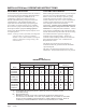
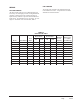
TABLE 4 FURNACE DATA Mo del N umber B urner Type Furnace Type N o z z le Siz e Type P ump P ressure 0.75 * FC 085D 36F A FG C ounterflow 0.65 70° Hollow 100 PSIG 0.55 0.75 * FH 085D 36F A FG Hi -Boy 0.65 70° Hollow 100 PSIG 0.55 0.85 * FH 110D 48F FH 110D 60F FLF085D 36F NX NX A FG Hi -Boy 60° Soli d FLR 110D 60F A FG 64,000 140,000 116,000 0.75 * 105,000 87,000 91,000 76,000 77,000 64,000 140,000 116,000 119,000 99,000 140,000 116,000 119,000 99,000 0.
1. PREPARATION STEPS A. Calibrate and Check Operation of Measuring Equipment Follow manufacturer’s recommended procedures for calibration and equipment check out. B. Prepare Heating Unit for Testing Drill two 1/4 inch holes in the flue between the heating plant and the barometric draft regulator. If space permits, the holes should be located in a straight section of the flue, at least two flue diameters from the elbow in the flue pipe and at least one diameter from the draft regulator.
1. Air leaks into the combustion chamber or heat exchanger can dilute the combustion gases and prevent normal CO2 readings. Such leaks should be sealed with furnace cement or other high-temperature sealant. To check for dilution by leakage, measure the CO2 at as high a point as possible over the fire, using a stainless steel tube inserted through the fire door sample hole (as described earlier for overfire draft measurements), and compare this with the CO2 measured in the flue.
FIGURE 8 TYPICAL SMOKE – CO2 CHART WITH ADJUSTMENT RANGE High Air Settings Low Bacharach Smoke Number 8 CO2 Curve from plotted points 6 Plotted point Normal adjustment range 4 Tolerance to "knee" "Best" air setting 2 Plotted point Plotted point "Knee" 0 6 8 12 10 Percent CO2 in Flue Gas Technician's plotting area 8 Bacharach Smoke Number 14 6 4 2 0 6 Manual 2100-422M Page 22 of 42 8 12 10 Percent CO2 in Flue Gas 14 MIS-1827
FIGURE 9 PRESSURE GAUGE CONNECTION TO BLEED PORT Remove Bleed Port to attach pressure guage.
TABLE 5 — CORRELATION OF PERCENT OF CO2, O2 AND RESERVE AIR C arbo n D io xide Oxyge n R eserve Air (Appro x.) 15.4 15.0 14.5 0.0 0.6 1.2 0.0 3.0 6.0 14.0 13.5 13.0 2.0 2.6 3.3 10.0 15.0 20.0 12.5 12.0 11.5 4.0 4.6 5.3 25.0 30.0 35.0 11.0 10.5 10.0 6.0 6.7 7.4 40.0 45.0 50.0 TABLE 6 — NO. 2 FUEL OIL EFFICIENCY CHART (NET STACK TEMP. DEGREES F) % O2 200 250 300 350 400 450 500 550 600 650 700 750 800 % O2 1 89.6 88.4 87.3 86.2 85.1 84.0 82.9 81.7 80.6 79.5 78.4 77.
SPACING OF ELECTRODES COMBUSTION AIR REQUIREMENTS The electrodes should be spaced 5/32" apart. They should extend 1/16" beyond the end and 5/16" above the center of the nozzle tip as shown in Figures 10A & 10B. This furnace must be installed in a location where a sufficient supply of combustion air is available for the complete combustion of the fuel oil. Keep in mind that a certain amount of excess air is required as well to ensure complete combustion of the fuel oil.
FIGURE 11 COMBUSTION AIR BOOT ASSEMBLY AFG BURNER COMBUSTION AIR BOOT ASSEMBLY USE THIS KNOCKOUT FOR OIL LINE INTAKE AIR TUBE AFG BURNER ASSEMBLY REMOVE PUMP TO ASSEMBLE INNER AIR BOOT REMOVE KNOCKOUT IN LEFT SIDE INSERT OUTER AIR BOOT AND SECURE FLANGE TO UNIT MAKE ALL SETTINGS ACCORDING TO MANUAL FOR AIR BOOT.
APPLIANCES LOCATED IN CONFINED SPACES In unconfined spaces in buildings, infiltration may be adequate to provide air for combustion, ventilation, and dilution of flue gases. However, in buildings of unusually tight construction, additional air shall be provided using the method described under “All Air From Outdoors” in Figure 13. An unconfined space (such as an open basement) must have a minimum volume of 50 cubic feet per 1,000 BTUH of total of all appliances in area.
TABLE 9 MINIMUM VENTILATION OPENINGS Mo del Min. Ventilatio n Opening Square Inch FH085D 36F ALL VENTILATION AIR FROM OUTDOORS R eco mmended Opening (2 R equired) Siz e Sq. In. 240 8 x 16 128 FH110D 48F 280 9 x 18 162 FH110D 60F 280 9 x 18 162 F LF 085D 36F 290 8 x 19 152 FLR085D 36F 290 8 x 19 152 FLF110D 48F FLF110D 60F 340 9 x 19 171 FLR110D 48F FLR110D 60F 340 9 x 19 171 FLR140D 60F 360 9.5 x 19 180 F C 085D 36F 240 8 x 16 128 A.
FIGURE 14 APPLIANCES LOCATED IN CONFINED SPACES ALL AIR FROM OUTDOORS THROUGH VENTILATED ATTIC NOTE: The inlet and outlet air openings shall each have a free area of not less than one square inch per 4,000 BTU per hour (35 square inches per gallon per hour) of the total input rating of all appliances in the enclosure.
LOUVERS AND GRILLES In calculating free area for ventilation and combustion air requirements, consideration shall be given to the blocking effect of louvers, grilles, or screens protecting openings. Screens used shall not be smaller than 1/4 inch (6.3 mm) mesh and shall be readily accessible for cleaning. If the free area through a design of louver or grille is known, it shall be used in calculating the size opening required to provide the free area specified.
TABLE 10 TEMPERATURE RISE RANGES, LIMIT CONTROL SETTINGS, AND HEATING BLOWER SPEEDS Mo del N umber N o z z le B urner Type R ise R anges Siz e Type P ump P ressure 0.75 * FC 085D 36F FH 085D 36F A FG A FG 0.65 60 - 90 70° Hollow 100 PSIG 60 - 90 Medi um Low 0.65 70° Hollow 100 PSIG 150 PSIG 150 PSIG Low 0.75 * 60 - 90 Medi um 0.65 70° Hollow 100 PSIG 150 PSIG 150 PSIG Medi um Low Medi um Hi gh 200 0.75 60 - 90 Medi um Low 0.75 * 60 - 90 Medi um 0.
AIR FILTERS Only Lo-Boy models are shipped with air filters. Filter kits are available from your local distributor for Upflow and Counterflow models. Knockouts are provided in the sides of the FH series models to facilitate the cutting of the return openings. TABLE 11 FILTER SIZES FOR OIL FURNACES Model The upflow filter kit part numbers are FR23 for a 16x25x1 filter size and FR24 for a 20x25x1 filter size.
LO-BOY MODELS – FILTER LOCATIONS Lo-boy models have the filter installed in the return air cabinet section of the furnace. It is accessible from the rear of the furnace by removing the blower/filter access door. The electrical switch should be turned “off” prior to removing the access door. Refer to Figure 18 below.
MAINTENANCE LUBRICATION No lubrication is required for either the burner or the blower motor. Both are permanently lubricated. INSPECT AIR FILTER Replace filters before each heating season begins. It is recommended that filters also be replaced at least twice during the heating season. Be sure the new filters are set securely in the filter rack so there can be minimal leakage around them.
COMBINATION COMBUSTION CHAMBER/BURNER MOUNTING SYSTEM The furnace has been designed with a combustion chamber mounting system that enables service personnel to remove the combustion chamber, its mounting system, and burner assembly as one unit for inspection and/or service on the bench. It has also been designed to remove the burner assembly independently from the mounting system to perform basic annual service and inspection.
TO REMOVE BURNER ONLY Disconnect fuel line, power cord and wires from T, T on primary control. Loosen (3) 1/4 inch bolts securing burner mounting flange. Twist burner counterclockwise and pull straight back away from the furnace. (See Figure 19.) TO REMOVE THE ENTIRE COMBUSTION CHAMBER MOUNTING SYSTEM Disconnect fuel line, power cord and wires from T, T on primary control. Remove (6) 5/16 inch bolts from around front plate.
COMMON CAUSES OF TROUBLE CAUTION To avoid accidents, always open main switch (OFF position) when servicing the burner. BURNER WILL NOT PRODUCE FLAME Check oil level gauge to see that there is sufficient oil in tank or tanks. Check the burner mounted relay control. Do not adjust this control. Check position of electrodes – incorrect position will cause slow or delayed ignition. Clean electrodes and nozzle. Check and clean strainer in pump. If oil line filter is used, check filter condition.
BLOWER SYSTEM RESISTANCE CHARTS CHART 1 FH085D36F DATA Blow er Speed CHART 4 FLF/FLR085D36F DATA Blow er Speed Blow er Static Blow er Static Low .10 .15 .23 .30 Low .07 .13 .19 .25 Medium .16 .24 .34 .43 Medium .15 .24 .33 .41 High .20 .30 .40 .50 High .20 .30 .40 .50 CHART 5 FLF/FLR110D48F DATA CHART 2 FH110D48F DATA Blow er Speed Blow er Static Blow er Speed Blow er Static Low .03 .08 .13 .18 Low .05 .09 .15 .20 Medium Low .09 .16 .23 .
CHART 8 FC085D36F DATA CHART 7 FLR140D60F DATA Blow er Speed Blow er Speed Blow er Static Blow er Static Low .05 .14 .17 .24 Low .08 .14 .20 .26 Medium Low .08 .17 .22 .30 Medium .16 .24 .36 .42 Medium High .11 .20 .27 .35 High .20 .30 .40 .50 High .20 .30 .40 .
FH SERIES WIRING DIAGRAM UNIT BACKUP LIMIT BURNER ASS'Y IGNITOR CAD CELL CAD CELL BLACK IGNITOR BLACK BURNER MOTOR BLACK BURNER MOTOR BLACK OIL VALVE BLACK WHITE TT L1 L2 VALVE PRIMARY LIMIT CONTROL HEAT EXCHANGER AREA PURPLE PURPLE PURPLE PURPLE BLACK BLACK BLACK DOOR SWITCH HIGH VOLTAGE SEE CHART FOR HEATING AND COOLING WIRE COLORS BLUE ORANGE RED WHITE BLACK 1 2 3 4 5 BROWN BLOWER CAPACITOR FIELD WIRING BLOWER ASSEMBLY Manual 2100-422M Page 40 of 42 UNIT FH085D36F FH110D48
Manual 2100-422M Page 41 of 42 IGNITOR CAD CELL IGNITOR CAD CELL BLACK BLUE ORANGE RED WHITE BLOWER ASSEMBLY BROWN BROWN 1 2 1 2 3 4 5 BLOWER CAPACITOR BLACK BURNER MOTOR BURNER MOTOR BLACK OIL VALVE L1 L2 VALVE BURNER ASS'Y BLACK 150 180 210 240 SEE CHART FOR "HEAT" AND "COOL" WIRE COLORS.
IGNITOR CAD CELL IGNITOR CAD CELL BLACK BLACK BLACK BLACK RED WHITE BLACK BLUE BLOWER ASSEMBLY (1/3 HP) BROWN BROWN BLOWER CAPACITOR (5/370) DOOR SWITCH BURNER MOTOR BURNER MOTOR BACKUP LIMIT OIL VALVE L1 L2 VALVE BURNER ASS'Y 1 2 3 4 5 1 2 3 4 1 2 150 180 210 240 3 BLOWER CONTROL R W G Y C PURPLE PURPLE SEE CHART FOR "HEAT" AND "COOL" WIRE COLORS.