INSTALLATION INSTRUCTIONS SPLIT AIR CONDITIONER OUTDOOR SECTION Models: HAC181-AD040 HAC241-AD040 HAC301-AD040 HAC361-AD040 HAC421-AD040 HAC481-AD040 HAC481-BD040 HAC601-AD040 HAC601-BD040 FOR USE WITH: MATCHING INDOOR BLOWER COIL UNITS AND MATCHING ADD ON COIL UNITS ONLY Bard Manufacturing Company Bryan, Ohio 43506 Since 1914 . . . Moving ahead just as planned. Manual No.
CONTENTS Split Air Conditioner General Information ......... 1 Wiring Instructions .............................................. 9 Split Air Conditioner Model Nomenclature ............... 1 General .................................................................... 9 Control Circuit Wiring ............................................... 9 Wall Thermostats ..................................................... 9 Optional Controls ...................................................
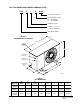
SPLIT AIR CONDITIONER MODEL NOMENCLATURE HAC 36 1 – A DXXX Customized Unit Code Electrical Characteristics A – 230/208-60-1 B – 230/208-60-3 Modification Code Capacity – 3 Ton or approx. 36,000 BTU Basic Model Number FIGURE 1 UNIT DIMENSIONAL DRAWING W ALTERNATE ELECTRICAL ENTRANCES ON BACK H HIGH VOLTAGE ENTRANCE LOW VOLTAGE ENTRANCE C REFRIGERANT SHUTOFF VALVES B F D A E MIS-1789 TABLE 1 UNIT DIMENSIONS "W" Width "D" Depth "H" Height A B C E F HAC181 HAC241 40.00 15.00 26.00 5.
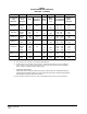
TABLE 2 RATED CFM AND AIR FLOW DATA (WET COIL – COOLING) Rated Airflow Condensing Unit Model No. Evaporator Coil Model No. CFM Pressure Drop H2O A30AS-A S24AS-A BC24B 650 650 650 .15 .24 A30AS-A S24AS-A BC24B 800 780 750 .18 .30 HAC301-A A36AS-A BC36B 1,000 1,000 .20 HAC361-A A37AS-A BC36B 1,100 1,100 .18 HAC421-A A42AS-A A48AS-A BC36B BC60B 1,400 1,500 1,200 1,500 .30 .26 HAC481 -A,-B A61AS-B BC60B 1,700 1,700 .28 HAC601-A,-B A61AS-B BC60B 1,760 1,800 .
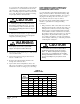
TABLE 3 SPECIFICATIONS MODELS HAC181-A HAC241-A HAC301-A HAC361-A HAC421-A HAC481-A HAC481-B HAC601-A HAC601-B Electrical Rating (60HZ / V/ PH) 230/208-1 230/208-1 230/208-1 230/208-1 230/208-1 230/208-1 230/208-3 230/208-1 230/208-3 Operating Voltage Range 197 - 253 197 - 253 197 - 253 197 - 253 197 - 253 197 - 253 187 - 253 197 - 253 187 - 253 Minimum Circuit Ampacity 15 15 19 20 25 26 17 35 21 ¬ Field Wire Size 14 14 12 12 10 10 12 8 10 ! Delay Fuse Maximum or Ci
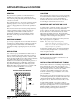
APPLICATION and LOCATION GENERAL LOCATION These instructions explain the recommended method to install the air cooled remote type condensing unit, the interconnecting refrigerant tubing and the electrical wiring connections to the unit. The condensing unit is designed to be located outside with free and unobstructed condenser air inlet and discharge. It must also permit access for service and installation.
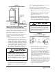
FIGURE 3 INSTALLING REFRIGERANT TUBING NOTE: Do not braze line to units! If orifice needs to be changed, change out orifice first. If the orifice does not have to be changed, skip the instructions outlined further in Step 3 and proceed to Step 8. 3. Disassemble Flow Control Assembly by turning body hex. 4. If existing orifice has not dropped out of the body when disassembled, remove by using a pin or paper clip. Discard this original orifice. 5.
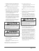
A copper-silver alloy with a high silver content should be used when iron or steel material is involved in the joint. These alloys require the use of silver solder flux. Alloys containing phosphorus should not be used with iron or steel. Phosphorus reacts with the iron forming iron phosphate which is extremely brittle. CAUTION FIELD FABRICATED TUBING CONNECTIONS: QUICK CONNECT INDOOR UNIT and SWEAT OUTDOOR UNIT USING CTO KIT Use only refrigeration grade (dehydrated and sealed) copper tubing.
2. The tubing ends should be cut square. Make sure it is round and free of burrs at the connecting ends. Clean the tubing to prevent contaminants from entering the system. NOTE: Do not make any tubing connection at indoor unit at this time. Make all brazing of joints and evacuate both suction and liquid line first. 3. Wrap a wet rag around the copper stub before brazing. 4. Flux the copper tube and insert into the stub.
16. Lubricate male half diaphragm and synthetic rubber seal with refrigerant oil. Thread coupling halves together by hand to insure proper mating of threads. Be sure to hold the coupling firmly to prevent movement of the coupling and tubing. Failure to do so could tear out the diaphragm causing a blockage of the system. Use proper size wrenches (on coupling body hex and on union nut) and tighten until coupling bodies ”bottom” or a definite resistance is felt.
WIRING INSTRUCTIONS GENERAL Example: All wiring must be installed in accordance with the National Electrical Code and local codes. In Canada, all wiring must be installed in accordance with the Canadian Electrical Code and in accordance with the regulations of the authorities having jurisdiction. Power supply voltage must conform to the voltage shown on the unit serial plate. A wiring diagram of the unit is attached to the inside of the electrical cover.
Manual 2100-346 Page 10
Manual 2100-346 Page 11
INSTALLATION INSTRUCTIONS — CMA-6 OPTIONAL CONTROLS FIGURE 5 COMPONENT MOUNTING LOCATION CMA-5 & CMA-13A LOW AMBIENT FAN CYCLING CONTROL TERMINAL BLOCK CMA-5 COMPRESSOR TIME DELAY RELAY Disconnect all power to unit. Remove control panel inner and outer cover. 1. Mount terminal block in position shown in Figure 5. 2. Disconnect black high voltage outdoor motor lead from compressor contactor and reconnect to terminal block. 3.
INSTALLATION INSTRUCTIONS – CMA-10A Disconnect all power to unit. Remove control panel cover. 1. Screw compressor control module and terminal block into control panel as shown in Figure 5. 2. Disconnect yellow low voltage wire form compressor contactor and reconnect to terminal “Y” of the compressor control module. 3. Connect the yellow wire from the compressor control module to “Y” side of the compressors contactor coil. This is the same terminal from which the wire was removed in Step 2. 4.
INSTALLATION INSTRUCTIONS – CMA-13A the high voltage outdoor motor lead was removed in Step 7. Disconnect all power to unit. Remove control panel cover. 1. Screw compressor control module and terminal block into control panel as shown in Figure 5. 2. Disconnect yellow low voltage wire from compressor contactor and reconnect to terminal “Y” of the compressor control module. 3. Connect the yellow wire from the compressor control module to “Y” side of the compressor’s contactor coil.
CHARGING INSTRUCTIONS PRESSURE SERVICE PORTS TABLE 9 SYSTEM SUPERHEAT High and low pressure service ports are installed on all units so that the system operating pressures can be observed. Pressure tables can be found later in the manual covering all models. It is imperative to match the correct pressure table to the unit by model number. SYSTEM START-UP (INDOOR UNITS WITHOUT EXPANSION VALVES) 1. Close disconnect switch(es) and set the thermostat to cool and the temperature to the highest setting.
TABLE 11 SCHEDULE FOR TABLE 11 TOTAL SYSTEM OPERATING CHARGE (Includes charge for the basic outdoor unit, indoor coil and 25’ of interconnecting tubing.) Outdoor Section Indoor Section Total R-22 Charge (Oz.) HAC181-A A30AS-A S24AS-A BC24B 73 oz. 73 oz. 78 oz. Q HAC241-A A30AS-A S24AS-A BC24B 80 oz. 80 oz. 79 oz. R HAC301-A A36AS-A BC36B 84 oz. 95 oz. R HAC361-A A37AS-A BC36B 98 oz. 96 oz. R HAC421-A A42AS-A A48AS-A BC36B BC60B 102 oz. 117 oz. 105 oz. 142 oz.
SERVICE SERVICE HINTS FIGURE 10 FAN BLADE 1. Caution homeowner to maintain clean air filters at all times. Also, not to needlessly close off supply and return air registers. This reduces air flow through the system, which shortens equipment service life, as well as, increasing operating costs. C 2. Check all power fuses or circuit breakers to be sure that they are the correct rating. 3. Periodic cleaning of the outdoor coil to permit full and unrestricted air flow circulation is essential.
Manual 2100-346 Page 18
Manual 2100-346 Page 19
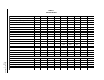
TABLE 13 PRESSURE TABLE HAC181-A Air Temperature Entering Outdoor Coil Indoor Section AS30AS-A S24AS-A BC24B Return Air Temp.
TABLE 15 PRESSURE TABLE HAC301-A Air Temperature Entering Outdoor Coil Indoor Section A36AS-A BC36B Return Air Temp.
TABLE 17 PRESSURE TABLE HAC 421-A Air Temperature Entering Outdoor Coil Indoor Section A42AS-A BC36B A48AS-A BC60B Return Air Temp.
TABLE 19 PRESSURE TABLE HAC601-A, HAC601-B Air Temperature Entering Outdoor Coil Indoor Section A61AS-B BC60B Return Air Temp.