INSTALLATION INSTRUCTIONS I-TEC SERIES PACKAGED HEAT PUMP Models: I30H1-A I30H1-B I30H1-C I36H1-A I36H1-B I36H1-C I42H1-A I42H1-B I42H1-C I48H1-A I48H1-B I48H1-C I60H1-A I60H1-B I60H1-C I30H1DA I30H1DB I30H1DC I36H1DA I36H1DB I36H1DC I42H1DA I42H1DB I42H1DC I48H1DA I48H1DB I48H1DC I60H1DA I60H1DB I60H1DC MIS-2957 A Bard Manufacturing Company, Inc. Bryan, Ohio 43506 www.bardhvac.
CONTENTS Getting Other Information and Publications For More Information, Contact These Publishers:.......... 3 General & ANSI Z535.5 Definitions........................... 4 I-TEC General Information I-TEC Model Nomenclature........................................ 5 Shipping Damage, Unit Removal From Skid................. 8 Handling Unit After Removal From Skid...................... 8 Required Steps after Final Placement......................... 9 Minimum Installation Height................................
GETTING OTHER INFORMATION AND PUBLICATIONS These publications can help you install the air conditioner or heat pump. You can usually find these at your local library or purchase them directly from the publisher. Be sure to consult current edition of each standard.
GENERAL The equipment covered in this manual is to be installed by trained, experienced service and installation technicians. The I-TEC must be installed with the Bard manufactured IWS wall sleeve and ILG louver grille accessories. These are sold as separate accessories. Any substitutions will void the manufacturer’s warranty. The unit is designed for use with or without ductwork. For use without ductwork, Plenum Box IPBDF8color (8" height) or IPBDF12-color (12" height) is recommended.
I-TEC Series General Information I-TEC MODEL NOMENCLATURE I 36 MODEL SERIES H 1 D A SYSTEM TYPE HEAT PUMP NOMINAL CAPACITY 30 – 30,000 BTUH 36 – 36,000 42 – 42,000 48 – 48,000 60 – 60,000 0Z R P SPECIAL UNITS (–) – Standard D – Dehum. VOLTS & PHASE A – 230/208, 60-1 B – 230/208, 60-3 C – 460-60-3 X X 1– 2– 3– 4– FILTER OPTIONS P – 2" Pleated MERV 8 M – 2" Pleated MERV 11 N – 2" Pleated MERV 13 VENTILATION OPTIONS B – Blank-Off Plate M – Multi-Speed CRV N – Comb.
TABLE 2 ELECTRICAL SPECIFICATIONS MODEL I30H1-A0Z A05 A10 I30H1-B0Z B06 B09 I30H1-C0Z C06 C09 I36H1-A0Z A05 A10 A15 I36H1-B0Z B06 B09 B15 I36H1-C0Z C06 C09 C15 I42H1-A0Z A05 A10 A15 I42H1-B0Z B06 B09 B15 I42H1-C0Z C06 C09 C15 I48H1-A0Z A04 A05 A10 A15 A20 I48H1-B0Z B06 B09 B15 B18 I48H1-C0Z C06 C09 C15 C18 I60H1-A0Z A05 A10 A15 A20 I60H1-B0Z B06 B09 B15 B18 I60H1-C0Z C06 C09 C15 C18 Rated No.
Manual 2100-549L Page 7 of 59 1 24" Front Forklift Holes (Remove Front Trim) 13 4 " 1 5 58" 3 Side Forklift Holes (Remove Sides) 1 22 4 " Lower Section 71 4 " Upper Section 94" Total Height 15 8 " Locking Door Latch Electrical Disconnect Locking Door Latch (4) Lift-Off Hinges High Voltage 7 Entrance 11 8 " Electric Heat Wire Channel 30" With Doors and Sides Removed Right Side View 1 24 2 " 1 71 2 " Outer Sleeve Inner Sleeve Return Air (2) Return Openings 3 34" 8" 1 38" Suppl
SHIPPING DAMAGE Upon receipt of equipment, the unit should be checked for external signs of shipping damage. The skid must remain attached until the unit is ready for installation. If damage is found, the receiving party must contact the last carrier immediately, preferably in writing, requesting inspection by the carrier’s agent. UNIT REMOVAL FROM SKID WARNING This unit is heavy and requires more than one person to handle during installation and removal from the skid.
REQUIRED STEPS AFTER FINAL PLACEMENT The compressor is secured to the base with two (2) bolts for shipping. Although the unit will perform as designed with the shipping bolts in place, there may be a noticeable additional noise and vibration noted. To obtain the lowest noise and vibration levels, remove the shipping bolts after the unit is in its final operating location. To gain access to the compressor, the compressor access panel must be removed (Figure 9).
RISER KIT NONE IRP-3 (3") IRP-6 (6") DIM A 31"-34" MAX 34"-37" MAX 37"-40" MAX Optional Duct DIM B 29 17/32" 32 17/32" 35 17/32" DIM C 94 1/8" 97 1/8" 100 1/8" Wall Section View BRACKET WALL SECTION VIEW Optional Top Bracket Outside Wall Ceiling Optional Trim or Supply Duct Box (4) optional Unit Mounting holes Telescoping Wall Sleeve** 7 7 20 8 " 20 8 " Sleeve Mounting Hole Locations Centered on Opening Outside Wall 3" 3 43 8 " 6" Centered 20" 42-3/4" Min. 43-1/4" Max. DIM C 48" Min.
FIGURE 3 CENTER OF GRAVITY CENTER OF GRAVITY "Z" "X" "Y" UNIT TESTED MIS-3269 FRONT OF UNIT DOOR TO CENTER LEFT SIDE TO CENTER FLOOR TO CENTER CRV & ERV FLOOR TO CENTER NO VENT "X" Dimension "Y" Dimension "Z" Dimension "Z" Dimension I30H1-A, -B 14" 24" 43½" 47" I30H1-C 14" 24¼" 43½" 47" I36H1-A, -B 14" 24" 43½" 47" I36H1-C 14" 24¼" 43½" 47" I42H1-A, -B 14" 24" 43½" 47" I42H1-C 14" 24¼" 43½" 47" I48H1-A, -B 14" 24" 43½" 47" I48H1-C 14" 24¼" 43½" 47" I60H
FIGURE 4 REQUIRED CLEARANCES & RECOMMENDED ACCESS WING WALL CONSTRUCTION TOP VIEW 12" MIN. 12" MIN. IMPORTANT Unit can be located in corner with 0" clearance as long as other side is unobstructed CLOSET CONSTRUCTION TOP VIEW 31 3/8" 12" MIN. 12" MIN. 12" MIN. 12" MIN. 48" MIN. RECOMMENDED SERVICE ACCESS DIMENSIONS 12" MIN. FOR LEFT SIDE ACCESS 12" MIN. FOR RIGHT SIDE ACCESS LEFT CORNER CONSTRUCTION TOP VIEW FILTERS 24" MIN. 24" MIN. 0" REQUIRED 12" RECOMENDED REMOVABLE SIDES 1 48" MIN.
FIGURE 5 COMPRESSOR SHIPPING BOLTS COMPRESSOR SHIPPING BOLT COMPRESSOR SHIPPING BOLT FIGURE 6 REMOVAL OF AIR DUCT CRV/ERV AIR DUCT Manual 2100-549L Page 13 of 59
Manual 2100-549L Page 14 of 59 7'-9 3/4" UNIT HEIGHT SUSPENDED CEILING 20" MINIMUM BOTTOM OF ROOF OR FIXED CEILING 9'-7" MINIMUM CLEARANCE RECOMMENDED TO BOTTOM OF ROOF OR FIXED CEILING FLOOR 4" MINIMUM FROM TOP OF UNIT TO DUCT BOTTOM 12" MINIMUM MIS-2958 B 9'-2" MINIMUM REQUIRED INSTALLATION HEIGHT TURNING VANES RECOMMENDED FIELD SUPPLIED DUCT FIGURE 7A DUCTED APPLICATION – BASIC UNIT
3" RISER 7'-9 3/4" UNIT HEIGHT SUSPENDED CEILING 20" MINIMUM BOTTOM OF ROOF OR FIXED CEILING 9'-10" MINIMUM CLEARANCE RECOMMENDED TO BOTTOM OF ROOF OR FIXED CEILING FLOOR 4" MINIMUM FROM TOP OF UNIT TO DUCT BOTTOM 12" MINIMUM FIELD SUPPLIED DUCT MIS-2989 B 9'-5" MINIMUM REQUIRED INSTALLATION HEIGHT TURNING VANES RECOMMENDED FIGURE 7B 3" RISER APPLICATION Manual 2100-549L Page 15 of 59
Manual 2100-549L Page 16 of 59 6" RISER 7'-9 3/4" UNIT HEIGHT SUSPENDED CEILING 20" MINIMUM BOTTOM OF ROOF OR FIXED CEILING 10'-1" MINIMUM CLEARANCE RECOMMENDED TO BOTTOM OF ROOF OR FIXED CEILING FLOOR 4" MINIMUM FROM TOP OF UNIT TO DUCT BOTTOM 12" MINIMUM TURNING VANES RECOMMENDED MIS-2988 B 9'-8" MINIMUM REQUIRED INSTALLATION HEIGHT FIELD SUPPLIED DUCT FIGURE 7C 6" RISER APPLICATION
DUCT WORK Any heat pump is more critical of proper operating charge and an adequate duct system than a straight air conditioning unit. All duct work must be properly sized for the design airflow requirement of the equipment. Air Conditioning Contractors of America (ACCA) is an excellent guide to proper sizing. All duct work or portions thereof not in the conditioned space should be properly insulated in order to both conserve energy and prevent condensation or moisture damage.
CONDENSATE DRAIN WITH COMMERCIAL ROOM VENTILATOR There are two condensate drain connections from the condenser drain pan (compressor area). These are visible from the rear of the unit. Factory installed tubing connects the two drains at a tee connection and then a single drain hose with a barbed hose connector carries the condensate to the draining option of your choice. Enough tubing is provided to reach all drain options and can be cut down in length. 1. Open hinged front doors. 2.
FIGURE 11A UNIT MOUNTING Use (12) Field Supplied Concrete or Wood Screws to Secure Outer Sleeve to Structure. IMPORTANT! Apply Caulk bead to entire perimeter seam between inner and outer sleeve. IMPORTANT! Apply liberal amount of caulk to back of flange before installing. REF. A REF.
FIGURE 11B UNIT MOUNTING Manual 2100-549L Page 20 of 59
INSTALLATION INSTRUCTIONS MOUNTING THE UNIT WIRING – MAIN POWER The wall sleeve is attached to the I-TEC unit from the outside of the building. See Figures 11A & 11B. Refer to wall sleeve Manual 2100-562 supplied with sleeve. Refer to the unit rating plate and/or Table 2 for wire sizing information and maximum fuse or circuit breaker size. Each unit is marked with a “Minimum Circuit Ampacity”. This means that the field wiring used must be sized to carry that amount of current.
WIRING – LOW VOLTAGE WIRING 230/208V, 1 PHASE AND 3 PHASE EQUIPMENT DUAL PRIMARY VOLTAGE TRANSFORMERS All equipment leaves the factory wired on 240V tap. For 208V operation, reconnect from 240V to 208V tap. The acceptable operating voltage range for the 240 and 208V taps are as noted in Table 3.
FIGURE 13 BASIC HEAT PUMP WITH NO VENTILATION PACKAGE Completestat Model #CS9B-THO or Model #CS9BE-THO SC SC SC 24V COM G Y1 Y2 O/B W2 L W1/E A GND D Yellow 3 2 Blue Orange White Red Thermostat Bard #8403-060 R C G Y1 Y2 O/B W2 L W1/E A 4 YO/D 2 3 Low Voltage Term. Strip R RT C G Y1 Y2 B/W1 W2 W3 L A D 6 3 4 1 1 Factory installed jumper. Remove jumper and connect to N.
FIGURE 14 HEAT PUMP WITH CRV, WITHOUT CO2 CONTROL SC SC SC 24V COM G Completestat Model #CS9B-THO or Model #CS9BE-THO Y1 Y2 O/B W2 L W1/E A GND D Yellow 3 Orange 2 Blue White 6 Red Thermostat Bard #8403-060 R C G Y1 Y2 O/B W2 W1/E L A YO/D 2 Low Voltage Term. Strip R RT C G Y1 Y2 W2 B/W1 1 W3 L 3 A D 6 4 3 5 4 RED/WHITE BLACK/WHITE ORANGE BROWN/WHITE CRV Wiring Harness 1 Factory installed jumper. Remove jumper and connect to N.
FIGURE 15 HEAT PUMP WITH CRV AND CO2 CONTROL SC SC SC 24V COM G Completestat Model #CS9B-THO or Model #CS9BE-THO Y1 Y2 O/B W2 L W1/E A D GND Yellow 3 2 Blue Orange White 7 Red Thermostat Bard #8403-060 R C G Y1 Y2 O/B W2 W1/E L A YO/D NOTE: Bard 8403-060 thermostat must be in programmed 3 operation mode and in programmed fan mode for ventilation to function. 2 Low Voltage Term.
FIGURE 16 HEAT PUMP WITH ERV, WITHOUT CO2 CONTROL SC SC SC 24V COM G Completestat Model #CS9B-THO or Model #CS9BE-THO Y1 Y2 O/B W2 L W1/E A GND D Yellow 3 2 Blue Orange White Red 6 Thermostat Bard #8403-060 R C G Y1 Y2 O/B W2 W1/E L A YO/D NOTE: Bard 8403-060 thermostat must 3 be in programmed operation mode and in programmed fan mode for ventilation to function. 2 Low Voltage Term.
FIGURE 17 HEAT PUMP WITH ERV AND CO2 CONTROL (ON/OFF CYCLING) Completestat Model #CS9B-THO or Model #CS9BE-THO SC SC SC 24V COM G Y1 Y2 O/B W2 L W1/E A D GND Yellow 3 2 Blue Orange White 7 Red Thermostat Bard #8403-060 R C G Y1 Y2 O/B W2 L W1/E A YO/D NOTE: Bard 8403-060 thermostat must 3 be in programmed operation mode and in programmed fan mode for ventilation to function. 2 Low Voltage Term.
FIGURE 18 HEAT PUMP WITH ERV AND CO2 CONTROL (FULLY MODULATING) Completestat Model #CS9B-THO or Model #CS9BE-THO SC SC SC 24V COM G Y1 Y2 O/B W2 L W1/E A D GND Yellow 3 2 Blue Orange White 6 Red Thermostat Bard #8403-060 R C G Y1 Y2 O/B W2 L W1/E A YO/D NOTE: Bard 8403-060 thermostat must be in programmed 3 operation mode and in programmed fan mode for ventilation to function. 2 Low Voltage Term.
FIGURE 19 HEAT PUMP WITH COMBINATION CRV AND DB ECONOMIZER (“N” VENT CODE) Only Recommend Bard CS9B-THOC or CS9BE-THOC as Require 3 Heating/Cooling Stages Completestat Model #CS9B-THOC or Model #CS9BE-THOC SC SC SC 24V COM G Y0 Y1 Y2 O/B W2 W1/E L A GND D 3 2 Yellow Orange Blue White 5 Red Low Voltage Term.
START UP THESE UNITS REQUIRE R-410A REFRIGERANT AND POLYOL ESTER OIL. REMEMBER: When adding R-410A refrigerant, it must come out of the charging cylinder/tank as a liquid to avoid any fractionation, and to insure optimal system performance. Refer to instructions for the cylinder that is being utilized for proper method of liquid extraction. GENERAL 1. Use separate service equipment to avoid cross contamination of oil and refrigerants. 2. Use recovery equipment rated for R-410A refrigerant. 3.
DESCRIPTION OF STANDARD EQUIPMENT Solid State Electronic Heat Pump Control Provides efficient 30, 60 or 90-minute defrost cycle. A thermistor sensor and speed up terminal for service along with a 8-minute defrost override are standard on the electronic heat pump control. By default, the I-TEC are factory shipped on the 90-minute defrost cycle. High/Low Pressure Switch Provides refrigerant circuit high pressure and loss of charge protection.
SEQUENCE OF OPERATION PRESSURE SERVICE PORTS COOLING PART LOAD – Circuit R-Y1 makes at thermostat pulling in compressor contactor, starting the compressor and outdoor motor. The G (indoor motor) circuit is automatically completed on any call for cooling operation or can be energized by manual fan switch on subbase for constant air circulation. High and low pressure service ports are installed on all units so that the system operating pressures can be observed.
DEFROST CYCLE The defrost cycle is controlled by temperature and time on the solid state heat pump control. See Figure 20. When the outdoor temperature is in the lower 40°F temperature range or colder, the outdoor coil temperature is 32°F or below. This coil temperature is sensed by the coil temperature sensor mounted near the bottom of the outdoor coil.
I-TEC COMMERCIAL ROOM VENTILATOR SYSTEM GENERAL DESCRIPTION The I-TEC Commercial Room Ventilator (CRV) is designed to be used with all Bard I-TEC models. The only intent of this device is to provide the required ventilation by delivering fresh air to meet I.A.Q. (Indoor Air Quality) requirements. In the installed application, this system also includes exhaust provisions which are balanced with the intake air to maintain building pressurization requirements of ASHRAE 62.1 Standard.
REMOVE TO DISASSEMBLE, DO NOT OVERTIGHTEN BOLTS WHEN REPLACING IMP level needed in accordance Suction Discharge (Low) (High) UNIT TIE PLATE Front Trim Piece 7961-754-2 corresponding CFM 3 PHASE LINE MONITOR CODES HP. BOARD TROUBLESHOOTING CODES with Figure 21. DESCRIPTION Open front swinging doors of main unit (byCODE popping DESCRIPTION CODE GREEN PHASES CORRECT, Y SIGNAL SLOW BLINK NORMAL OPERATION front door latches). LIGHT PRESENT FAST BLINK COMPRESSOR TIME DELAY 1 BLINK PRESS. SWITCH 1.
FIGURE 22 CRV SPEED CHANGE TERMINAL ACCESS CRV INTAKE BLOWER NOTE: CRV EXHAUST BLOWER IS BEHIND INTAKE BLOWER REMOVE (5) SCREWS FROM CRV DOOR TO ACCESS CRV COMPONENTS MIS-3023 BLOWER SPEED CONTROL LOCATION BLOWER SPEED CONTROL BLOWER REMOVED FOR CLARITY Manual 2100-549L Page 36 of 59
I-TEC COMBINATION CRV AND ECONOMIZER VENTILATION SYSTEM DESCRIPTION The I-TEC combination Commercial Room Ventilator (CRV) and Dry Bulb Economizer is designed to be used with all Bard I-TEC models. This ventilation package and its control provides two (2) roles: • It will provide the required ventilation by delivering fresh air to meet I.A.Q. (Indoor Air Quality) requirements through CRV portion of the device.
I-TEC ECON. SEQUENCE OF OPERATION • If outdoor temperature is below outdoor thermostat setpoint On call from CompleteStat for first stage cooling: • “YO” thermostat signal powers vent blower motors at Economizer Speed/Airflow (black – 525 CFM) through NC contacts of Relay “R1” (“Dehum Relay”). On call from CompleteStat for first and second stage cooling: • “YO” thermostat signal powers vent blower motors at Economizer Speed/Airflow (black – 525 CFM) through NC contacts of Relay “R1” (“Dehum Relay”).
HEATING MODE OPERATION VENTILATION MODE CompleteStat should never energize “YO” terminals in conjunction with “B”, so relay “R2” will never energize, and neither will Economizer Ventilation Speed. The call for ventilation will never be disrupted with this control circuit. Anytime “A” signal from CompleteStat is present, the “VENTILATION SPEED” of the vent package will be energized.
I-TEC ENERGY RECOVERY VENTILATOR SYSTEM GENERAL DESCRIPTION The I-TEC Energy Recovery Ventilator (ERV) was designed to provide energy efficient, cost effective ventilation to meet I.A.Q (Indoor Air Quality) requirements while still maintaining good indoor comfort and humidity control for a variety of applications such as schools, classrooms, lounges, conference rooms and others.
RECOMMENDED CONTROL SEQUENCES 5. Locate two 0-10Vdc Motor Control Boards in control panel (see Figure 28). Several possible scenarios are listed below: 6. On intake Motor Control Board, observing “GREEN 1. Use a programmable electronic thermostat with REV.
PERFORMANCE AND APPLICATION DATA SUMMER COOLING PERFORMANCE (INDOOR DESIGN CONDITIONS 75°DB/62°WB) Ambient O.D.
ERV "MANUAL MODE" JUMPERFIGURE PIN ON25A "M" Terminal ERV "MOD ERV “MANUAL MODE” JUMPER PIN ON “M” TERMINAL ERV CFM 450 To adjust the airflow ventilation rate (NO CO2 FLOW INDEX (Light CONTROL/NON-MODULATING) , determine the "FLOW Blink Code) INDEX" needed for the intake and exhaust blowers for the CFM you require.
FIGURE 26 VENTILATION AIRFLOW DIAGRAM Supply Air SUPPLY BLOWER Return Air Outdoor Air VENT INTAKE BLOWER Indoor Air VENT EXHAUST BLOWER MIS-3024 Manual 2100-549L Page 44 of 59
FIGURE 27 ERV ACCESS ERV INTAKE BLOWER NOTE: ERV EXHAUST BLOWER IS BEHIND INTAKE BLOWER ERV CASSETTE ASSEMBLIES MIS-3025 REMOVE (5) SCREWS FROM ERV DOOR TO ACCESS ERV COMPONENTS ERV CONTROL PANEL LOCATION Manual 2100-549L Page 45 of 59
Bulletin AQ-CDT e 24 Vac side of the power transformer4. Connect the ACU+ neutral connection to the earthed lead. Series CDT Carbon Dioxide/Temperature Transmitter 50/60Hz connection to the hot side of the 24 Vac Class II power source. With the “P” jumper out, Specifications - Installation s connection as a means to stop the ECM Motor. Most automation controllersand will Operating power the Instructions a 24 Vac on/off output, eliminating the fan relay.
fIGURE 5: Active Output Diagram Use maximum 18 AWG wire for cover wiringtotobase terminals. any power. temperature are on notthe polarity 5. Reattach plate. Refer to Figure 5 for wiringThermistor and Passive RTD passive outputs outputs are located back sensitive. plate and doWiring not require Useinformation. maximum 18 AWG wire for wiring to terminals. Refer to Figure 5 for wiring any power. Passive temperature outputs are not polarity sensitive.
MENU DESCRIPTIONS RON Relay on set point Sets the CO2 concentration which the optional relay is energized. Low limit: 0 PPM Factory setting: 1000 PPM High limit: 2000/5000 PPM (depending on model) ROF Relay off set point Sets the CO2 concentration which the optional relay is de-energized. Setting value lower than RON provides direct action for detecting high concentrations of CO2. Setting value higher than RON provides indirect action for detecting low concentrations of CO2.
ENERGY RECOVERY VENTILATOR MAINTENANCE GENERAL INFORMATION The ability to clean exposed surfaces within air moving systems is an important design consideration for the maintenance of system performance and air quality. The need for periodic cleaning will be a function of operating schedule, climate, and contaminants in the indoor air being exhausted and in the outdoor air being supplied to the building.
ANNUAL MAINTENANCE 1. Inspect and conduct the same procedures as outlined under Quarterly Maintenance. 2. To maintain peak latent (moisture) removal capacity, it is recommended that the energy recovery wheels be sprayed with a diluted nonacid based evaporator coil cleaner or alkaline detergent solution such as 409. NOTE: Do not use acid based cleaners, aromatic solvents, temperatures in excess of 170° F or steam. Damage to the wheel may result.
TROUBLESHOOTING SOLID STATE HEAT PUMP CONTROL TROUBLESHOOTING PROCEDURE 1. NOTE: A thorough understanding of the defrost cycle sequence is essential. Review that section earlier in this manual prior to troubleshooting the control. Turn on AC power supply to unit. 2. Turn thermostat blower switch to “fan on”— the indoor blower should start. (If it doesn’t, troubleshoot indoor unit and correct problem.) 3. Turn thermostat blower to “auto” position. Indoor blower should stop. 4.
CHECKING TEMPERATURE SENSOR 3. Check resistance reading to chart of resistance use sensor ambient temperature. (Tolerance of part is ±10%.) 1. Disconnect temperature sensor from board and from right-hand outdoor coil. 2. Use an ohmmeter and measure the resistance of the sensor. Also use ohmmeter to check for short or open. 4. If sensor resistance reads very low, then sensor is shorted and will not allow proper operation of the heat pump control. 5.
4.250 2.585 WARNING EXPOSED MOVING PARTS. DISCONNECT ALL ELECTRICAL POWER BEFORE SERVICING. FAILURE TO DO SO CAN RESULT IN SEVERE INJURY OR AMPUTATION. WARNING HAZARD OF ELECTRICAL SHOCK. ELECTRICAL SHOCK CAN RESULT IN SERIOUS INJURY OR DEATH. DISCONNECT THE REMOTE ELECTRIC POWER SUPPLY OR SUPPLIES BEFORE SERVICING. 7961-755-1 ! MOTOR SPEEDS VENT OPTION INTAKE/EXHAUST SPEEDS 1. In normal operation, this motor may rock WIRE COLOR SPEED NOM. CFMback and forth on start up.
TABLE 7 TROUBLESHOOTING ECM™ 142R OUTDOOR FAN MOTOR Check between Red and Black Wires for Line Power Check Line Power to Motor Verify Ground by checking Green Wire to L1 and L2 Line Power Check "BR" terminal of Fan Logic Control Board Check for 24VAC common signal to motor (against Transformer "R" Signal) Check "Blue" Fan Lead on "Fan Relay Terminal" of "Defrost Logic Control" ** Is not energized in cooling mode until Low Ambient Fan Cycling Control is closed by 325 PSIG refrigerant pressure.
TROUBLESHOOTING INDOOR ECM™ BLOWER MOTORS CAUTION: Symptom Cause/Procedure Disconnect power from unit before removing or replacing connectors, or servicing motor. To avoid electric shock from the motor’s capacitors, disconnect power and wait at least 5 minutes before opening motor. • Noisy blower or cabinet • Check for loose blower housing, panels, etc.
Replacing ECM Control Module To replace the control module for the GE variable-speed indoor blower motor you need to take the following steps: 1. You MUST have the correct replacement module. The controls are factory programmed for specific operating modes. Even though they look alike, different modules may have completely different functionality. USING THE WRONG CONTROL MODULE VOIDS ALL PRODUCT WARRANTIES AND MAY PRODUCE UNEXPECTED RESULTS. 2. Begin by removing AC power from the unit being serviced.
TROUBLESHOOTING ECMTM BLOWER MOTORS MODE of OPERATION OFF Thermostat 24 VAC Inuput Signals — Pin #1 Continuous Blower (Ventilation Mode) "G" Part Load Cooling Full Load Cooling "G", "Y1","Y2" "G", "Y1","Y2" Dehum. Mode (when equipped) "D" Part Load Heat Pump Full Load Heat Pump "G", "B", "Y1" "G", "B", "Y1", "Y2" Heat Pump Full Load w/ 1st Bank of Elec. Heat "G", "Y1", "Y2", "B", "W1" Heat Pump Full Load w/ 1st & 2nd Bank of Elec.
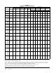
TABLE 10A FULL LOAD COOLING PRESSURE/TEMPERATURE Model I30H1 I36H1 I42H1 I48H1 I60H1 AIR TEMPERATURE ENTERING OUTDOOR COIL °F Return Air Temp.
TABLE 11A PART LOAD COOLING PRESSURE/TEMPERATURE Model I30H1 I36H1 I42H1 I48H1 I60H1 AIR TEMPERATURE ENTERING OUTDOOR COIL °F Return Air Temp.