
Specifications


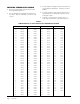

Manual 2100-549L
Page 51 of 59
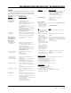
TROUBLESHOOTING
SOLID STATE HEAT PUMP CONTROL
TROUBLESHOOTING PROCEDURE
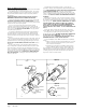
1. NOTE: A thorough understanding of the defrost
cycle sequence is essential. Review that section
earlier in this manual prior to troubleshooting the
control. Turn on AC power supply to unit.
2. Turn thermostat blower switch to “fan on”—
the indoor blower should start. (If it doesn’t,
troubleshoot indoor unit and correct problem.)
3. Turn thermostat blower to “auto” position. Indoor
blower should stop.
4. Set system switch to “heat” or “cool”. Adjust
thermostat to call for heat or cool. The indoor
blower, compressor and outdoor fan should start.
NOTE: If there was no power to 24 volt transformer,
the compressor and outdoor fan motor will not
start for 5 minutes. This is because of the
compressor short cycle protection.
CODES FUNCTION
Slow Blink Normal Operation
Fast Blink Compressor Time Delay
1 Blink Low Pressure Switch Failure
2 Blink High Pressure Switch Failure
or Condensate Overflow
Switch Activated
3 Blink Defrost Mode Active
4 Blink High Pressure or Overflow
Switch Lockout
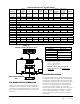
Symptom Description, Check & Possible Causes What & How to Check / Repair
Compressor will not
start (heating or
cooling)
1. Check for LED illumination.
Is there an LED illuminated on the board (flashing)?
Yes = go to Step #2; No = go to Step #3
2. Check for error codes.
Is the LED flashing a Code?
Yes = go to Step #4; No = go to Step #8
3. Check for power at board.
Is there 24 volts AC between R and C?
Yes = go to Step #13; No = go to Step #9
4. Check codes.
What code is blinking?
Code "1", go to Step #6; Code "2", go to Steps #7A & #7B; Fast Blink,
go to Step #5
5. Compressor delay active.
Wait for 5 minute delay or jump board's "speed up pins".
Check for proper operation; if still needed, go back to Step #1.
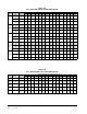
6. Low pressure fault. Check wiring circuit and unit pressures.
7A. High pressure fault. Check wiring circuit and unit pressures.
7B. Condensate overflow fault.
Check upper indoor coil drains; check lower outdoor coil drains; check
main drain line.
8. Check for Compressor input signal.
Is there 24 volts AC between Y and C?
Yes = go to Step #10; No = go to Step #11
9. No power to board.
The unit either does not have unit voltage, the transformer is bad or the
unit wiring is incorrect.
10. Check for Compressor output signal.
Is there 24 volts AC between CC & C?
Yes = go to Step #12; No = go to Step #13
11. No "Y" compressor input signal.
Check thermostat wiring, incorrect phase of unit (see section on Phase
Monitor), and finally unit wiring.
12. No "CC" compressor output signal.
Check compressor contactor for proper operation and finally check
compressor.
13. Faulty board. Replace defrost board.
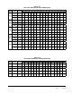
Fan outdoor motor
does not run
(cooling or heating
except during
defrost)
Heat pump control defective
Check across fan relay on heat pump control. (Com-NC) Replace heat
pump control.
Motor defective Check for open or shorted motor winding. Replace motor.
Motor capacitor defective
Check capacitor rating. Check for open or shorted capacitor. Replace
capacitor.
Reversing valve does
not energize
(heating only)
Heat pump control defective
Check for 24V between RV-C and B-C.
1. Check control circuit wiring.
2. Replace heat pump control
Reversing valve solenoid coil defective Check for open or shorted coil. Replace solenoid coil.
Unit will not go into
defrost
(heating only)
Temperature sensor or heat pump control defective
Disconnect temperature sensor from board and jumper across
"SPEEDUP" terminals and "SEN JMP" terminals. This should cause the
unit to go through a defrost cycle within one minute.
1. If unit goes through defrost cycle, replace temperature sensor.
2. If unit does not go through defrost cycle, replace heat pump control.
Unit will not come
out of defrost
(heating only)
Temperature sensor or heat pump control defective.
Jumper across "SPEEDUP" terminal.
This should cause the unit to come out of defrost within one minute.
1. If unit comes out of defrost cycle, replace temperature sensor.
2. If unit does not come out of defrost cycle, replace heat pump control.
TABLE 5
TROUBLESHOOTING