
Specifications


Manual 2100-549L
Page 54 of 59
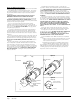
Check Line Power to Motor
Check between Red and Black Wires for Line Power
Verify Ground by checking Green Wire to L1 and L2 Line Power
Check for 24VAC common signal to motor
(against Transformer "R" Signal)
Check "BR" terminal of Fan Logic Control Board
Check "Blue" Fan Lead on "Fan Relay Terminal" of "Defrost Logic Control"
** Is not energized in cooling mode until Low Ambient Fan Cycling Control is closed by 325
PSIG refrigerant pressure.
** Circuit is completed automatically when "B" is energized on the Fan Logic Control Board
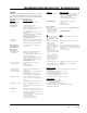
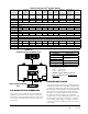
Check 24VAC "hot" outputs (to "Blue" on Fan Logic Control) to motor. See the following tables based upon outdoor temperature and model of
operation.
O.D. Temp Sensor 24VAC Signals Between
Below 55°F Orange to Blue
Between 56° - 69°F White to Blue
Between 70° - 85°F Yellow to Blue
Between 86° - 112°F Orange and White to Blue
Above 112°F White and Yellow to Blue
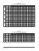
O.D. Temp Sensor 24VAC Signals Between
Above 56°F Orange to Blue
Between 55° - 30°F White to Blue
Between 29° - 14°F Yellow to Blue
Below 13°F Orange and White to Blue
If the output signals are not matching the specified temperature range, then go to Table #6 and verify the thermistor
output curve. If the motor is receiving proper communications and proper high voltage power, and is still not
running, proceed with Motor Replacement. (When checking the resistance/temperature curve, don’t forget about the
optional 2.2k ohm fan control resistor assembly.)
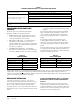
TROUBLESHOOTING FAN LOGIC
CONTROL
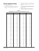
Please reference the Thermistor Temperature/
Resistance Chart in this manual (Table 6).
• GREEN STATUS LED – Blinks indicating there is
a call for fan operation (simultaneous to call for
compressor operation) and is normal.
• RED STATUS LIGHT (LA) – Is illuminated when
low ambient control switch is in the closed
position. (NOTE: This is not required in heat pump
operation as the low ambient switch is bypassed in
this mode of operation.)
• YELLOW STATUS LIGHT (B) – Is illuminated
when there is a reversing valve call (for heat pump
operation). (NOTE: As mentioned above, this mode
of operation negates the low ambient fan cycling
control.)
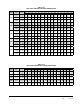
If the board is reading a fan temperature thermistor
value of 3375Ω or less (equivalent to 125°F or an
"open" sensor), the fan will operate at the highest
speed setting (energizes "W" and "Y" outputs on the
board).
If the board is reading a fan temperature value
of 118,110Ω or greater (equivalent to -10°F or a
"shorted" sensor), the fan will operate at the highest
speed setting (energizes "W" and "Y" outputs on the
board).
If the low ambient switch is open, the red light will not
be illuminated and the "BR" terminal will show open.
The "BR" terminal is the "24 volt common" switching
output to the outdoor fan motor.
TABLE 7
TROUBLESHOOTING ECM™ 142R OUTDOOR FAN MOTOR
TABLE 8
COOLING MODE
TABLE 9
HEAT PUMP MODE
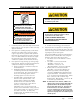
REPLACING THE MOTOR
This motor is replaced in one piece. The control
cannot be replaced separately from the motor. Even if
the control is remotely located, the replacement part
will be a new control with harness and new motor.
You must have the correct replacement motor from the
manufacturer that is a direct replacement for the failed
motor.
USING THE WRONG MOTOR VOIDS ALL PRODUCT
WARRANTIES AND MAY PRODUCE UNEXPECTED
RESULTS.
Always mount the replacement motor and control
according to the manufacturers specifications using
all required hardware to reduce vibration. Make sure
all wires are free of the fan blade and not pinched in
mountings or cabinet through points.