
Product Overview


The MC4002 has 2 stages of cooling control available
for each connected air conditioner. It is designed for
systems with or without economizers and for systems with
2-stage or dual compressors. The 2
nd
stage available for
each air conditioner permits complete and proper control
when economizers are installed or when 2-stage or dual
compressors are utilized. With the addition of a simple 2
wire humidity controller as an input signal, it can provide
electric reheat dehumidification circuit. The controller can
also be configured for use with heat pumps. (NOTE: The
electric reheat dehumidification feature is not available when
configured for heat pumps).
The MC4002, either in basic form or when equipped with
optional alarm relay boards, is a fully functional controller
with unique configurable capability. The MC4002 can be
ordered as a basic controller only or factory equipped with
one of two variations of alarm boards with varying amounts
of alarm capabilities to fit the user’s requirements. Ethernet
communication option is also available.
If only the base controller is initially installed, it can be easily
upgraded by simple snap-in of the alarm relay board and
plug-in of the communication cable to the main controller
board. Form C dry contact alarm relays are used, offering
both NO and NC switching to meet the user’s specific alarm
protocol, providing complete flexibility to meet any user’s
requirements. All alarm actuations are individually indicated
on the controller front panel, along with indication for active
stages of cooling or heating, and which unit is currently
“lead”. A digital display indicates building temperature and
is also used for all of the programming functions.
Controller:
• Electronic (non-mercury) design
• Programmable
• Works with or without economizers
• Dehumidification control option
• Can be used with heat pumps
Alarm Boards:
• Can be specified with or without alarm boards
• Alarms boards can be added at any time
• Alarm circuits can be NO or NC logic
Communication Board:
• Ethernet remote access for all controller functions
• Can be factory or field installed
• IPV6 with SNMP traps
Ease of Installation:
• Powered by 24V from A/C units
• Phasing of 24V from units is not required
• Durable metal enclosure adequately sized for ease
of conduit and wire installation
Certifications & Approvals:
• Complies with FCC Rule 15, Subpart B, Class A
• This ISM device also complies w/Canadian ICES-001
• Complies with CE Standards EN55011/EN50081
and EN55024 for ISM Equipment, Class A
• ETL Conforms to UL916 Standard for Energy
Management Equipment, Certified to CSA STD
C22.2 No. 205
AB3000-A Base Alarm Board
AB3000-B Enhanced Alarm Board
MC4002 Controller no alarms
MC4002-A Controller with Base Alarm Board
MC4002-B Controller with Enhanced Alarm Board
MC4002-AC Controller w/Base Alarm & Ethernet Board
MC4002-BC
Controller w/Enhanced Alarm & Ethernet Board
with SNMP Traps & IPV6
Key Design Features
Controller Models Available
Alarm Board Add-Ons (Field-Installed)
MC4002 Series Advanced Solid State Dual Unit Lead/Lag
Controller with Ethernet Remote Communication Option
CB5000 Ethernet Communication Board with
SNMP Traps and IPV6
Communication Board Add-Ons (Field-Installed)
• 20-Gauge Gray Pre-Painted Metal
• 9.25" W x 13.50" H x 3" D
• Hinged Cover
• Thirteen (13) .875" Diameter Knockouts
Controller Enclosure
8612-023A Remote Temperature Sensor w/35' Cable
Optional Equipment
Form No. S3548-1116
Supersedes NEW
Page 1 of 8
CONFORMS TO UL STD 916
CERTIFIED TO
CSA STD C22.2 NO. 205
7961-731
Comfort Mode
Press “Comfort” button once to reset to 72F/22C
Cooling and 68F/20C Heating for 1-hour. Display
will flash during override period. Press 2nd-time to
cancel during override if desired, or controller will
automatically revert to selected SP after 1-hour.
1. To swap lead and lag units press “ADVANCE”.
2. To enter the Program mode press the
“Program” button and release it when “Pro9”
appears. Use “DOWN” or “UP” arrows to
scroll through menu.
3. A “Flashing” display means that the function
or choice is “Set”, and the display will alternate
between the step function and setting.
4. To change the setting of any step press
the “Change” button and the display will
stop flashing, allowing change to the
setting by using the “Down” or “Up” arrows.
When desired setting is reached press the
“Save” button, and proceed as desired.
5. When done programming press the
“Program” button until display stops flashing
and room temperature is shown. If no buttons
are pushed within 30-seconds the controller
will automatically revert back to “Run” mode.
Operating Instructions
1st
Stage
2nd
Stage
Unit
#1
Unit
#2
3rd
Stage
4th
Stage
Cooling
Heating
Digital
Display
Dehumid.
Operation
Lead
Unit
1st
Stage
2nd
Stage
3rd
Stage
4th
Stage
Power Loss Sys. 1
Fire/Smoke Alarm
Low Temp. Alarm
High Temp. Alarm 1
High Temp. Alarm 2
Lead/Lag Controller
Failure Alarm
Power Loss Sys. 2
Refrig. Alarm Sys. 1
Refrig. Alarm Sys. 2
AB3000-B Alarm Board Functions
AB3000-A Alarm Board Functions
On
Off
Program
Advance
Change
Save
Comfort
Alarms
Alarm boards are optional
and can be factory or field
installed. See inside of
controller for any alarm
functions.
Solid State Dual Unit Lead Lag Controller
MC Series
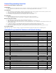
Program Menu
NOTE: Push and hold Up or Down arrows for 1-second
until display blanks to move between steps.
1 Temperature at local (main) Sensor
2 Temperature at Remote 1 sensor location*
3 Temperature at Remote 2 sensor location*
4 Cooling setpoint temperature
(65 to 90F or 18.3 to 32.2C - Default is 77F/25C)
5 Deadband between cooling and heating setpoint
(2 to 40F or 1.1 to 22.2C - Default is 17F/9.4C)
6 Continuous blower operation
(None, Lead, Both - Default is None)
7 Degree display (F or C - Default is F)
8 Alternating Lead-Lag-Lead-Lag Sequence or
Non-Alternating Lead-Lead-Lag-Lag Sequence
(Yes or No - Default is Yes for Alternating)
9 Lead-Lag changeover time (Days)
(1 to 30 days, or 0 for disabled - Default is 7)
10 Heat pump logic enabled - only for 1-stage
heat pumps and forces Lead-Lag sequence
and overrides a Non-Alt setting
(Yes or No - Default is No)
11 Unit 1 and 2 blowers automatically both run if
delta T>5F between any 2 connected sensors
(Yes or No - Default is Yes)
12 3-minute lead unit & 4-minute lag unit off-delay enabled (Yes or No - Default is No)
13 Minimum of 3-minute compressor runtime enabled (Yes or No - Default is No)
14 Low temperature alarm setpoint (28 to 65F or 21.1 to 48.8C - Default is 45F/7.2C)
15 High temperature alarm Level 1 setpoint
(70F to 120F or 21.1 to 48.8C - Default is 90F/32.2C)
16 High temperature alarm Level 2 setpoint (70F to 120F or 21.1 to 49C - Default is 95F/35C)
17 Inter-stage differential from Stage 1 to 2 (2, 3, 4, 5 or 6F - Default is 4)
18 Inter-stage differential from Stage 2 to 3 (2 or 3F - Default is 2)
19 Inter-stage differential from Stage 3 to Stage 4 (2 or 3F - Default is 2)
20 Turn “On” above SP for Stage 1 Cooling (+1 or +2 - Default is +2)
21 Turn “Off” below SP for Stage 1 Cooling (-1, -2, -3, or -4F - Default is -2)
Note: For CSon and CSoF Stage 2, 3 and 4 Cooling are automatically same as Stage 1
22 All Heating stages are equal -/+ On & Off differential (-1/+1 or -2/+2 - Default is -2/+2)
23 1 or 2-stage compressor, if set to 1 the 2nd-Stage Cooling Alarm activates on Cooling Call 2
If set to 2 the 2nd-Stage Cooling Alarm activates on Cooling Call 3. (1 or 2 - Default is 1)
24 Controller is Locked. Consult building authority for further instructions.
*
r1 and r2 will display temperature only if optional remote sensors are installed.
If sensors are not installed these are omitted in the display sequence. If r1 and/or r2 sensor
installed the MC controller will control to the “average” of the connected sensors.
Consult installation instructions for additional details.