INSTALLATION INSTRUCTIONS WALL MOUNTED VARIABLE CAPACITY ENVIRONMENTAL CONTROL UNITS MODELS W3RV1 W5RV1 W6RV1 W3LV1 W5LV1 W6LV1 Bard Manufacturing Company, Inc. Bryan, Ohio 43506 Since 1914...Moving ahead just as planned.
Contents Getting Other Information and Publications 3 Wall Mount General Information ECU Wall Mount Model Nomenclature .................... Shipping Damage .................................................... General ................................................................ Duct Work ................................................................ Filters ................................................................ Fresh Air Intake .......................................................
GETTING OTHER INFORMATION AND PUBLICATIONS These publications can help you install the air conditioner or heat pump. You can usually find these at your local library or purchase them directly from the publisher. Be sure to consult current edition of each standard. FOR MORE INFORMATION, CONTACT THESE PUBLISHERS: ACCA Air Conditioning Contractors of America 1712 New Hampshire Ave. N.W.
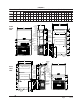
WALL MOUNT GENERAL INFORMATION Environmental Control Unit (ECU) Wall-Mount Model Nomenclature W 3 R V 1 – R REVISIONS MODEL SERIES Wall-Mount SYSTEM DESIGN SPECIAL FEATURES Variable Capacity 10 X R - Right Side L - Left Side X X X X - None Electric Heat @ Rated Voltage ELECTRICAL RATING R - 230/208-60-1 & 220/200-50-1 S - 230/208-60-3 & 220/200-50-3 T - 460-60-3 & 400-50-3 COLOR OPTIONS COIL OPTIONS X 1 4 5 6 A S X 1 2 3 - Beige (Standard) White Buckeye Gray Desert Brown Dark Bronz
DUCT WORK FILTERS All duct work, supply and return, must be properly sized for the design airflow requirement of the equipment. Air Conditioning Contractors of America (ACCA) is an excellent guide to proper sizing. All duct work or portions thereof not in the conditioned space should be properly insulated in order to both conserve energy and prevent condensation or moisture damage. A 1-inch throwaway filter is standard with each unit. The filter slides into position making it easy to service.
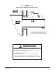
INSTALLATION INSTRUCTIONS WALL MOUNTING INFORMATION WARNING 1. Two holes for the supply and return air openings must be cut through the wall as shown in Figures 3A & 3B. 2. On wood frame walls, the wall construction must be strong and rigid enough to carry the weight of the unit without transmitting any unit vibration. Failure to provide the 1/4 inch clearance between the supply duct and a combustible surface for the first 3 feet of duct can result in fire causing damage, injury or death. 3.
FIGURE 2 Dimensions of Basic Unit for Architectural and I nstallation Requirements (Nominal) MODEL WIDTH DEPTH HEIGHT SUPPLY (W) (D) (H) A B RETURN C B E F G I J K L M N O P Q R S1 S2 T W3RV1 38.200 17.125 70.563 7.88 27.88 13.88 27.88 40.00 10.88 25.75 17.93 26.75 28.75 29.25 27.00 2.75 39.19 22.75 9.14 4.19 12.00 12.00 5.00 W3LV1 W5RV1 42.075 22.432 84.875 9.88 29.88 15.88 29.88 43.88 13.56 31.66 30.00 32.68 26.94 34.69 32.43 3.37 42.88 23.88 10.00 1.44 16.00 16.00 1.88 W5LV1 W6RV1 42.075 22.432 94.
Manual 2100-538E Page 8 of 23 1 D E 5" 12" 12" 12" 12" 12" D 1 42" 3" 4" Typ. 1" 28" 3 " 4" 8 Typ. Return Opening Supply Opening A 10 1 42" C Wall Opening and Hole Location View 7 8" C 30 1" 14" E B 4 1/2 4 9/16 16 7/8 C REQUIRED DIMENSIONS TO MAINTAIN RECOMMENDED 1" CLEARANCE FROM COMBUSTIBLE MATERIALS B 5 1/4 3 13/16 17 5/8 A REQUIRED DIMENSIONS TO MAINTAIN 28 1/2 8 1/2 1/4" MIN.
Manual 2100-538E Page 9 of 23 7 18" 16" 16" 16" 16" 16" 1 1 4" Typ. 1 1 62" 38" C 5 1/2 6 1/4 C Dimension is 21" on W6R and W6L Units. 4" Typ. 1" 3" 30" Return Opening Supply Opening A 12 10 1/2 B Wall Opening and Hole Location View 1 1 62" 1 62" C 32 REQUIRED DIMENSIONS TO MAINTAIN RECOMMENDED 1" CLEARANCE FROM COMBUSTIBLE MATERIALS D 30 1/2 REQUIRED DIMENSIONS TO MAINTAIN 1/4" MIN.
FIGURE 4 ELECTRIC HEAT CLEARANCE W3RV1, W3LV1, W5RV1, W5LV1, W6RV1, W6LV1 SIDE SECTION VIEW OF SUPPLY AIR DUCT FOR WALL MOUNTED UNIT SHOWING 1/4 INCH CLEARANCE TO COMBUSTIBLE SURFACES. WARNING A minimum of 1/4 inch clearance must be maintained between the supply air duct and combustible materials. This is required for the first 3 feet of ducting. It is important to insure that the 1/4 inch minimum spacing is maintained at all points.
FIGURE 5 WALL MOUNTING INSTRUCTIONS WALL STRUCTURE SEE FIGURES 3A & 3B – MOUNTING INSTRUCTIONS FACTORY SUPPLIED RAIN FLASHING. MOUNT ON UNIT BEFORE INSTALLATION SUPPLY AIR OPENING SUPPLY AIR OPENING SUPPLY AIR DUCT RETURN AIR OPENING RETURN AIR OPENING RETURN AIR OPENING BOTTOM MOUNTING BRACKET. MOUNT ON WALL BEFORE INSTALLING UNIT.
FIGURE 7 COMMON WALL MOUNTING INSTALLATIONS SUPPLY DUCT MAY BE LOCATED IN AN ATTIC OR BELOW CEILING RAFTERS AS SHOWN RAIN FLASHING RAFTERS RAIN FLASHING FINISHED CEILING SURFACE SUPPLY AIR DUCT SUPPLY AIR DUCT W/ GRILLE FINISHED CEILING SURFACE RETURN AIR OPENING W/ GRILLE RETURN AIR OPENING W/ GRILLE OUTSIDE WALL RAFTERS OUTSIDE WALL FREE AIR FLOW NO DUCT DUCTED SUPPLY RETURN AT UNIT SUPPLY DUCT MAYBE LOCATED IN AN ATTIC OR BELOW CEILING RAFTERS AS SHOWN RAIN FLASHING RAFTERS SUPPLY DUCT MAY
WIRING – MAIN POWER 240V to 208V tap. The acceptable operating voltage range for the 240 and 208V taps are: These units are rated for 60/50 Hz operation as follows. TAP 240 208 NOTE: This system must be controlled only by the Bard 8403-064 Digital Thermostat/Controller that is supplied with the unit. See below for Wiring and Pages 16-17 for Operating Sequences.
START UP THESE UNITS REQUIRE R-410A REFRIGERANT AND POLYOL ESTER OIL. REMEMBER: When adding R-410A refrigerant, it must come out of the charging cylinder/tank as a liquid to avoid any fractionation, and to insure optimal system performance. Refer to instructions for the cylinder that is being utilized for proper method of liquid extraction. GENERAL: 1. Use separate service equipment to avoid cross contamination of oil and refrigerants. 2. Use recovery equipment rated for R-410A refrigerant. 3.
START UP (Continued) IMPORTANT INSTALLER NOTE PHASE MONITOR For improved start up performance wash the indoor coil with a dish washing detergent. All units with three phase scroll compressors are equipped with a 3 phase 60/50 Hz line monitor to prevent compressor damage due to phase reversal. No changes required for 60 or 50 Hz operation. HIGH PRESSURE SWITCH All W*R/LV wall mounted air conditioner series models are supplied with a remote reset for the high and low pressure switch.
SEQUENCE OF OPERATION MODES OF OPERATION Cool Only Mode: • Compressor will modulate from 100% down to 20%. • Compressor will cycle off if thermostat/controller setpoint is reached. Heat Only Mode: • Electric heat Stage 1 operates at 1st-stage heating set-point. • Electric heat Stage 2 (if equipped) operates on 2nd stage (-2F below heating set-point). Auto Mode: • Cooling or heating automatically selected based on building temperature vs. thermostat/controller setpoints and operates as described above.
COOLING SEQUENCE Compressor Operation The cooling capacity of the WV series is controlled by loading or unloading the compressor. On a call for cooling, the unloader solenoid is energized for one second to ensure pressure equalization in the compressor. The compressor contactor, RLY 2, is then energized and the compressor will start. A PI control loop then calculates the compressor capacity needed to reach set point and modulates the compressor . Modulation range is from 20% to 100% capacity.
COMPRESSOR CONTROL MODULE Alarm Relay Output The compressor control module is standard on all models covered by this manual. The compressor control module is an anti-short cycle/lockout timer with high and low pressure switch monitoring and alarm relay output. Alarm terminal is output connection for applications where alarm relay is employed. This terminal is powered whenever the compressor is locked out due to HPC or LPC sequences as described.
TROUBLESHOOTING REMOVAL OF FAN SHROUD FAN BLADE SETTING DIMENSIONS Shown in Figure 8 is the correct fan blade setting for proper air delivery across the outdoor coil. Refer to Table 1 for unit specific dimension. Any service work requiring removal or adjustment in the fan and/or motor area will require that the dimensions below be checked and blade adjusted in or out on the motor shaft accordingly. 1. Disconnect all power to the unit. 2.
TABLE 2 COOLING PRESSURE TABLE Air Temperature Entering Outdoor Coil °F (°C) Model W3RV W3LV W5RV W5LV W6RV W6LV D.B/W.B. 1 75 80 85 90 95 100 105 110 115 120 125 131 Pressure (23.9) (26.7) (29.4) (32.2) (35.0) (37.8) (40.6) (43.3) (46.1) (48.9) (51.7) (55.0) 75 / 62F (23.9/16.7C) Low S i de High Side 128 355 127 373 127 394 127 416 128 442 129 469 130 498 132 530 135 565 80 / 67F (26.7/19.
Manual 2100-538E Page 21 of 23 460-60-3 400-50-3 230/208-60-3 220/200-50-3 460-60-3 400-50-3 230/208-60-3 220/200-50-3 230/208-60-1 220/200-50-1 460-60-3 400-50-3 230/208-60-3 220/200-50-3 230/208-60-1 220/200-50-1 1 1 1 or 2 1 1 1 1 1 1 1 1 or 2 1 or 3 1 1 2 1 1 1 1 2 2 1 1 1 No.
TABLE 4 RECOMMENDED AIRFLOW Mo del R ated C FM * R ated ESP * R eco mmended Airflo w R ange W3R/LV 1100 .15 1100 - 550 W5R/LV 1700 .20 1700 - 85 0 W6R/LV 1700 .20 1700 - 85 0 * Rated CFM and ESP on high speed tap. TABLE 5 MAXIMUM ESP OF OPERATION ELECTRIC HEAT ONLY W3 W5, W6 FRONT FRONT High High -A0Z -A05 -A10 .50 .50 .50 .50 .50 .50 -B0Z -B06 -B09 .50 .50 .50 .50 .50 .50 -C0Z -C09 -C12 .50 .50 .45 .50 .50 .
D escriptio n W5R/LV W6R/LV P art N umber W3R/LV TABLE 7 VENT & CONTROL OPTIONS C MC -15 Start Ki t (230V 1-Phase) X X BFAD -3 Barometri c Fresh Ai r D amper - Standard X BOP-3 Blank Off Plate X BFAD -5 Barometri c Fresh Ai r D amper - Standard X X BOP-5 Blank Off Plate X X Manual 2100-538E Page 23 of 23