INSTALLATION INSTRUCTIONS SINGLE PACKAGE AIR CONDITIONERS MODELS P1142A3 P1148A1 P1060A1 Bard Manufacturing Company Bryan, Ohio 43506 Since 1914 . . .
Contents Getting Other Informations and Publications ........ 1 General Instructions Important ................................................................ Shipping Damage .................................................... General ................................................................ Field-Installed Heater Packages (Optional) ............. Figure 1 4 4 4 4 Installation Location ................................................................ 6 Typical Installations .......................
Getting Other Information and Publications These publications can help you install the air conditioner or heat pump. You can usually find these at your local library or purchase them directly from the publisher. Be sure to consult current edition of each standard. For more information, contact these publishers: ACCA Air Conditioning Contractors of America 1712 New Hampshire Ave. N.W.
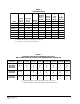
TABLE 1 ELECTRICAL DATA Q R Maximum External Fuses or Ckt. Brk. Minimum Circuit Ampacity Field Power Wiring Ground Wire Size Ckt. A Ckt. A Ckt. A Ckt. A R Rated Volts & Phases Operating Voltage Range Maximum Unit Amps P1142A3 230/208-1 197 - 253 24.2 45 29 8 10 P1148A1 240/208-1 197 - 253 26.1 50 36 8 10 P1148A1-B 230/208-3 187-253 18.8 35 23 8 10 P1148A1-C 460-3 414-506 8.5 20 13 12 12 P1060A1 230/208-1 197 - 253 33.
TABLE 3 OPTIONAL FIELD-INSTALLED ELECTRIC HEATER TABLE Htr. KW & Capacity @ 240V (or 480V if applicable) Circuit B Htr. KW & Capacity @ 208 Volts @ 240V R Q S or 480V as Heater No. Minimum Maximum Field Ground applicable Internal Field Circuit Overcurrent Power Wire Htr. Amps Fuses Ckts. Ampacity Protection Wiring Size Heater Pkg. Model Unit Volts No. Phase KW BT UH EH5PB-A05 EH5PB-A10 EH5PB-A15 EH5PB-A20 240/208-1 240/208-1 240/208-1 240/208-1 5 10 15 20 17,100 3.75 34,100 7.50 51,200 11.
GENERAL INSTRUCTIONS IMPORTANT The equipment covered in this manual is to be installed by trained, experienced service and installation technicians. All duct work, supply and return ducts, must be properly sized for the design air flow requirement of the equipment. ACCA is an excellent guide to proper sizing. All duct work or portions thereof not in the conditioned space should be properly insulated in order to both conserve energy and prevent condensation or moisture damage.
FIGURE 1 PREFABRICATED ROOF CURB SPECIFICATIONS HEAVY GAUGE GALVANIZED WITH WOOD NAILING STRIP, WELDED/LEAKPROOF ONE PIECE CONSTRUCTION – READY TO INSTALL MIS-1177 CURB AND ROOF DETAILS Roof Curb A 9042-004 82-3/8 B C* D E F J* H* Roof Hood Model 44-1/8 41-1/8 38-3/8 35-3/8 44 14-3/4 19-1/8 RHE60 *Duct Sizing Information Return Air Dimension “C” is length Return Air Dimension “H” is width Air Conditioning Units P1142A3, P1148A1, P1060A1 Supply Air Dimension “C” is length Supply Sir Di
INSTALLATION LOCATION GENERAL The unit must be located outside, or in a well ventilated area. It must not be in the space being heated or cooled. A sound absorbing material should be considered if the unit is to be installed in such a position or location that might cause transmission of sound or vibration to the living area or adjacent buildings. SLAB MOUNTING In areas where winter temperatures DO NOT go below 32° F for periods over twelve hours, the unit may be slab mounted at grade level.
FIGURE 3 ELEVATED MOUNTING PLATFORMS MIS-1183 FIGURE 4 AIRFLOW AND SERVICE ACCESS CLEARANCES MIS-1185 Manual 2100-324 Page 7
FIGURE 5 ROOF TOP APPLICATION (MAY ALSO BE REQUIRED FOR GROUND LEVEL INSTALLATIONS.
3. SLAB MOUNTED AT GROUND LEVEL – This type installation is ideal for homes with a slab floor construction where a roof mounted unit is not desired. The supply and return duct work can be run through a furred closet space. With a trap installed on a unit located in an unconditioned area, water in the trap may freeze. It is recommended that the trap material be of a type that will allow for expansion of water when it freezes. 4.
WIRING – MAIN POWER Refer to the unit rating plate for wire sizing information and maximum fuse size. Each outdoor unit is marked with a “Minimum Circuit Ampacity”. This means that the field wiring used must be sized to carry that amount of current. If field installed heaters are added to the basic unit, a second separate power supply circuit will be required. The heater rating plate located adjacent to the basic unit rating plate will show the appropriate circuit ampacity fuse size, etc.
FIGURE 8 LOW VOLTAGE WIRING MIS-1180 Manual 2100-324 Page 11
START UP AND OPERATION THREE PHASE SCROLL COMPRESSOR START UP INFORMATION Scroll compressors, like several other types of compressors, will only compress in one rotational direction. Direction of rotation is not an issue with single phase compressors since they will always start and run in the proper direction. However, three phase compressors will rotate in either direction depending upon phasing of the power.
ALARM OUTPUT ADJUSTMENTS Alarm terminal is output connection for applications where alarm signal is desired. This terminal is powered whenever compressor is locked out due to HPC or LPC sequences as described. ADJUSTABLE DELAY-ON-MAKE AND DELAY-ON-BREAK TIMER NOTE: Both high and low pressure switch controls are inherently automatic reset devices. The high pressure switch and low pressure switch cut out and cut in settings are fixed by specific air conditioner or heat pump unit model.
SERVICE AND TROUBLESHOOTING FIGURE 9 FAN BLADE SETTING DIMENSIONS SERVICE HINTS 1. Caution homeowner to maintain clean air filters at all times. Also, not to needlessly close off supply and return air registers. This reduces air flow through the system which shortens equipment service life as well as increasing operating costs. 2. Check all power fuses or circuit breakers to be sure that they are the correct rating. 3.
FIGURE 10 BRAZING DIAGRAM MIS-1179 TABLE 10 PRESSURE TABLE COOLING Air Temperature Entering Outdoor Coil Degrees F Model P1142A3 P1148A1 P1060A1 Return Air Pressure Temperature 75 80 85 90 95 100 105 110 115 75 deg. DB 62 deg. WB Low Side High Side 70 208 72 223 75 239 77 254 78 271 79 288 80 305 81 324 82 342 80 deg. DB 67 deg. WB Low Side High Side 75 213 77 229 80 245 82 261 84 278 85 295 96 313 87 332 88 351 85 deg. DB 72 deg.
Manual 2100-324 Page 16
Manual 2100-324 Page 17
Manual 2100-324 Page 18
Manual 2100-324 Page 19
Manual 2100-324 Page 20
Manual 2100-324 Page 21