INSTALLATION INSTRUCTIONS SINGLE PACKAGE HEAT PUMPS MODELS PH1224 PH1230 PH1236 Bard Manufacturing Company Bryan, Ohio 43506 Since 1914...Moving ahead, just as planned.
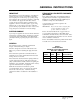
Contents Getting Other Informations and Publications ........ 1 General Instructions ................................................. Important ................................................................ Shipping Damage .................................................... General ................................................................ Field-Installed Heater Packages (Optional) .............. 3 3 3 3 3 Installation .................................................................
Getting Other Information and Publications These publications can help you install the air conditioner or heat pump. You can usually find these at your local library or purchase them directly from the publisher. Be sure to consult current edition of each standard. National Electrical Code ........................... ANSI/NFPA 70 Standard for the Installation ...................... ANSI/NFPA 90A of Air Conditioning and Ventilating Systems Standard for Warm Air .............................
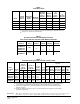
TABLE 1 ELECTRICAL DATA Q R Maximum External Fuses or Ckt. Brk. Minimum Circuit Ampacity Field Power Wiring Ground Wire Size Ckt. A Ckt. A Ckt. A Ckt. A R Rated Volts & Phases Operating Voltage Range Maximum Unit Amps PH1224 230/208-1 197 - 253 14.4 25 18 10 10 PH1230 230/208-1 197 - 253 17.7 30 22 10 10 PH1236 230/208-1 197 - 253 21.8 40 27 8 8 PH1236-B 230/208-3 197 - 253 15.6 25 19 10 10 Model Q R Maximum time delay fuse or HACR type circuit breaker.
GENERAL INSTRUCTIONS IMPORTANT The equipment covered in this manual is to be installed by trained, experienced service and installation technicians. Any heat pump is more critical of proper operating charge and an adequate duct system than a straight air conditioning unit. All duct work, supply and return ducts, must be properly sized for the design air flow requirement of the equipment. ACCA is an excellent guide to proper sizing.
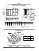
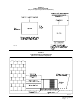
FIGURE 1 PREFABRICATED ROOF CURB SPECIFICATIONS HEAVY GAUGE GALVANIZED WITH WOOD NAILING STRIP, WELDED/LEAKPROOF ONE PIECE CONSTRUCTION – READY TO INSTALL MIS-1177 CURB AND ROOF DETAILS Roof Curb A 9042-003 80-3/8 B C* D E F J* H* Roof Hood Model 40-1/4 37-1/4 38-3/8 35-3/8 42 14-3/4 19-1/8 RHE60 *Duct Sizing Information Return Air Dimension “C” is length Return Air Dimension “H” is width Air Conditioning Units PH1224, PH1230, PH1236 Supply Air Dimension “C” is length Supply Sir Dimen
INSTALLATION LOCATION TYPICAL INSTALLATIONS GENERAL 1. ROOF MOUNTED – The unit is mounted on a sturdy base on the roof of the building. Return air to the unit is brought through a single return grille (grilles with built-in filters are best since they enable easy access for filter changing). Return air ducts are attached to the lower section of the front panel. Supply air is brought from the unit to attic duct work or to a furred down hall. Supply air duct is attached to the top of the front panel.
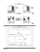
FIGURE 3 ELEVATED MOUNTING PLATFORMS MIS-1183 FIGURE 4 AIRFLOW and SERVICE ACCESS CLEARANCES MIS-1185 Manual 2100-344 Page 6
FIGURE 5 ROOF TOP APPLICATION (May also be required for ground level installations.
CONDENSATE DRAIN TRAP It is very important to provide a trap in the condensate drain line to allow a positive liquid seal in the line and assure correct drainage from the coil condensate pan. Install condensate drain trap shown in Figure 7. Use drain connection size or larger. Do not operate unit without trap. Unit must be level or slightly inclined toward drain. With a trap installed on a unit located in an unconditioned area, water in the trap may freeze.
WIRING – MAIN POWER Refer to the unit rating plate for wire sizing information and maximum fuse size. Each outdoor unit is marked with a “Minimum Circuit Ampacity”. This means that the field wiring used must be sized to carry that amount of current. If field installed heaters are added to the basic unit, a second separate power supply circuit will be required. The heater rating plate located adjacent to the basic unit rating plate will show the appropriate circuit ampacity fuse size, etc.
THERMOSTATS See specific wiring information for the different models, heater KWs, and voltages.
THERMOSTAT INDICATOR LAMPS The red lamp marked “EM. HT.” comes on and stays on whenever the system switch is placed in Em. Ht. position. The green lamp marked “Check” will come on if there is any problem that prevents the compressor from running when it is supposed to be. COMPRESSOR CUTOFF THERMOSTAT WIRING (5 and 10 KW) FIGURE 9 UNIT 24V TERMINAL BOARD EMERGENCY HEAT POSITION The operator of the equipment must manually place the system switch in this position.
START UP AND OPERATION THREE PHASE SCROLL COMPRESSOR START UP INFORMATION Scroll compressors, like several other types of compressors, will only compress in one rotational direction. Direction of rotation is not an issue with single phase compressors since they will always start and run in the proper direction. However, three phase compressors will rotate in either direction depending upon phasing of the power.
FIGURE 11 HEAT PUMP CONTROL BOARD MIS-1191 Manual 2100-344 Page 13
SERVICE AND TROUBLESHOOTING SERVICE HINTS 1. Caution homeowner to maintain clean air filters at all times. Also, not to needlessly close off supply and return air registers. This reduces air flow through the system which shortens equipment service life as well as increasing operating costs. 2. Switching to heating cycle at 75° F or higher outside temperature may cause a nuisance trip of the manual reset high pressure switch. 3. The heat pump wall thermostats perform multiple functions.
TROUBLE SHOOTING GUIDE Symptom Compressor contactor does not energize (heating or cooling) Fan outdoor motor does not run (cooling or heating except during defrost) Possible Causes What to Check How to Check or Repair Contil circuit wiring Check for R connection at unit Run R connection to outdoor unit to power heat and 24 volt between R-C. pump control. Compressor lock out 1. Check for 24V between 1.
CHECKING TEMPERATURE SENSOR CHECK OUT 3. Check resistance reading to chart of resistance; use sensor ambient temperature. (Tolerance of part is ± 10%.) 1. Disconnect temperature sensor from board and from outdoor coil. 4. If sensor resistance reads very low, then sensor is shorted and will not allow proper operation of the heat pump control. 2. Use an ohmmeter and measure the resistance of the sensor. Also use ohmmeter to check for short or open. 5.
• SUCTION AND DISCHARGE TUBE BRAZING Compliant Scroll compressors have copper plated steel suction and discharge tubes. These tubes are far more rugged and less prone to leaks than copper tubes used on other compressors. Due to different thermal properties of steel and copper, brazing procedures may have to be changed from those commonly used. • To disconnect: heat joint Areas 2 and 3 slowly and uniformly until braze material softens and the tube can be pulled out of suction fitting. (See Figure 10.
PRESSURE TABLES TABLE 11 COOLING Air Temperature Entering Outdoor Coil Degrees F Model PH1224 PH1230 PH1236 Return Air Temperature Pressure 75 80 85 90 95 100 105 110 115 75 deg. DB 62 deg. WB Low Side High Side 73 191 75 205 76 219 78 234 79 251 80 267 81 285 82 303 83 323 80 deg. DB 67 deg. WB Low Side High Side 78 196 80 210 81 225 83 240 84 257 88 274 87 292 88 311 89 331 85 deg. DB 72 deg.
Wiring Diagram (4098-123) printed from CAD to get size needed Manual 2100-344 Page 19
Wiring Diagram (4098-124) printed from CAD to get size needed Manual 2100-344 Page 20
Wiring Diagram (4098-211) printed from CAD to get size needed Manual 2100-344 Page 21