
HEAT PUMPS INSTALLATION INSTRUCTIONS MODELS PH1224 PH1230 PH1236

Manual 2100-344
Page 8
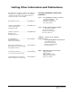
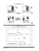
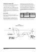
FIGURE 7
CONDENSATE DRAIN TRAP
MIS-136
maintained for proper operation. If this is not done,
excessive energy use, poor performance, and multiple
service problems will result. It is impossible to oversize air
filters. Generous sizing will result in cleaner air and coils
as well as lower operating costs and extend the time
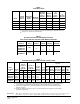
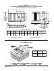
between required changes. Table 6 shows minimum filter
areas and recommended filter sizes. Actual filter sizes can
vary with the installation due to single or multiple returns
utilizing a filter/grille arrangement or being placed
immediately ahead of the indoor coil face in the return air
duct.
CONDENSATE DRAIN TRAP
It is very important to provide a trap in the condensate drain
line to allow a positive liquid seal in the line and assure
correct drainage from the coil condensate pan.
Install condensate drain trap shown in Figure 7. Use drain
connection size or larger. Do not operate unit without trap.
Unit must be level or slightly inclined toward drain. With a
trap installed on a unit located in an unconditioned area,
water in the trap may freeze. It is recommended that the trap
material be of a type that will allow for expansion of water
when it freezes.
AIR FILTERS
Air filters for the return air side of the system are not
provided as part of the various types of applications for these
models, and must be field supplied and installed as part of
the final installation.
Prior thought should be given to return air location and
placement of the air filter(s). The air filter(s) must be of
adequate size and readily accessible to the operator of the
equipment. Filters must be adequate in size and properly
TABLE 5
NOTE: If roof hood accessory is to be used, information
on air filters may be found under that heading in this
manual. Air filters are supplied as part of that package.
ledoM
retliFmuminiM
saerA
dednemmoceR
eziS
4221HP
0321HP
6321HP
sehcnierauqs264
)teeferauqs12.3(
1x8/5-03x51