
HEAT PUMPS INSTALLATION INSTRUCTIONS MODELS PH1224 PH1230 PH1236

Contents
Getting Other Informations and Publications ........ 1
General Instructions ................................................. 3
Important ................................................................ 3
Shipping Damage .................................................... 3
General ................................................................ 3
Field-Installed Heater Packages (Optional) .............. 3
Installation................................................................. 5
Location ................................................................ 5
Typical Installations .................................................. 5
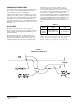
Condensate Drain Trap ............................................ 8
Air Filters ................................................................ 8
Wiring – Main Power................................................ 9
Wiring – 24V Low Voltage Control Circuit ................ 9
Thermostats ........................................................... 10
Thermostat Indicator Lamps ...................................11
Emergency Heat Position .......................................11
Transformer Taps ....................................................11
Compressor Cut-Off Thermostat and Outdoor
Thermostat Wiring ..................................................11
Start Up and Operation .......................................... 12
Three Phase Scroll Compressor Start Up
Information ............................................................. 12
Sequence of Operation .......................................... 12
Defrost Cycle ......................................................... 12
Start Up Notes ....................................................... 12
Service and Troubleshooting ................................ 14
Service Hints .......................................................... 14
Pressure Service Ports .......................................... 14
Refrigerant Charge ................................................ 14
Fan Blade Settings................................................. 14
Solid State Heat Pump Control
Troubleshooting Procedure .................................... 14
Troubleshooting Guide ........................................... 15
Checking Temperature Sensor Check Out............. 16
Temperature vs. Resistance of
Temperature Sensor Chart..................................... 16
Suction and Discharge Tube Brazing ..................... 17
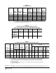
Pressure Tables ..................................................... 18
Wiring Diagrams ............................................. 19 - 21
Figures
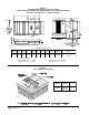
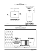
Figure 1 Prefabricated Rood Curb
Specifications .......................................... 4
Figure 2 Field Fabricated Curbing ......................... 4
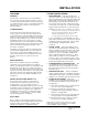
Figure 3 Elevated Mounting Platforms .................. 6
Figure 4 Airflow and Service Access
Clearances .............................................. 6
Figure 5 Roof Top Application ............................... 7
Figure 6 Slab Mounting at Ground Level ............... 7
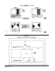
Figure 7 Condensate Drain Trap ........................... 8
Figure 8 Low Voltage Wiring ................................. 9
Figure 9 Compressor Cut-Off Thermostat
Wiring (5 and 10 KW) ............................11
Figure 10 Compressor Cut-Off Thermostat
Wiring )15 KW ONLY) ...........................11
Figure 11 Heat Pump Control Board ..................... 13
Figure 12 Fan Blade Setting Dimensions .............. 14
Figure 13 Brazing Diagram ................................... 17
Tables
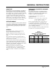
Table 1 Electrical Data ......................................... 2
Table 2 Optional Field Installed Heater
Packages ................................................ 2
Table 3 Optional Field Installed Heater Table ....... 2
Table 4 Rated CFM and Rated ESP.................... 3
Table 5 Air Filter Area and Size ........................... 8
Table 6 Thermostat Wire Size ............................. 9
Table 7 Heat Pump Thermostats ....................... 10
Table 8 Volts, KW and Phase - Compressor
Cut-Off Wiring (5 and 10 KW) ...............11
Table 9 Volts, KW and Phase - Compressor
Cut-Off Wiring (15 KW ONLY0 .............11
Table 10 Refrigerant Charge ............................... 14
Table 11 Pressure Table - Cooling ....................... 18
Table 12 Pressure Table - Heating ....................... 18