QTEC SERIES PACKAGED HEAT PUMP INSTALLATION INSTRUCTIONS Models: Q24H1 Q30H1 Q36H1 Q42H1 Q48H1 Q60H1 Bard Manufacturing Company, Inc. Bryan, Ohio 43506 Since 1914 . . . Moving ahead, just as planned. © Copyright 2009 Manual: Supersedes: File: Date: 2100-519 NEW Vol.
CONTENTS Getting Other Information and Publications For more information, contact these publishers: .......... 3 QTEC General Information QTEC Model Nomenclature .......................................... 4 Shipping Damage ......................................................... 7 Unit Removal From Skid .............................................. 7 Handling Unit After Removal From Skid ....................... 8 General .........................................................................
GETTING OTHER INFORMATION AND PUBLICATIONS These publications can help you install the air conditioner or heat pump. You can usually find these at your local library or purchase them directly from the publisher. Be sure to consult current edition of each standard.
QTEC Series General Information QTEC MODEL NOMENCLATURE Q 36 MODEL NUMBER Q - QTEC H 1 – A HEAT PUMP KW 0Z - 0KW 05 - 5KW 06 - 6KW 09 - 9KW 10 - 10KW 12 - 12KW 15 - 15KW REVISION CAPACITY | 24 - 2 Ton 30 - 2½ Ton 36 - 3 Ton 42 - 3½ Ton 48 - 4 Ton 60 - 5 Ton SPECIAL UNITS | L - Low Ampacity Circuit VOLTS & PHASE | A - 230/208/60/1 B - 230/208/60/3 C - 460/60/3 10 X X V X X X COIL OPTIONS X - Standard FILTER OPTIONS X - 1-Inch Fiberglass (Standard) F - 2-Inch Fiberglass P - 2-Inch Pleated
TABLE 2 ELECTRICAL SPECIFICATIONS Single Circuit Model Q24H1-A0Z A 05 A 10 Q24H1-B0Z B 06 B 09 Q24H1-C0Z C 06 C 09 Q30H1-A0Z A 05 A 10 Q30H1-B0Z B 06 B 09 B 12 Q30H1-C0Z C 06 C 09 C 12 Q36H1-A0Z A 05 A 10 4 A 15 Q36H1-B0Z B 06 B 09 5 B 15 Q36H1-C0Z C 06 C 09 5 C 15 Q42H1-A0Z A 05 A 10 4 A 15 Q42H1-B0Z B 06 B 09 5 B 15 Q42H1-C0Z C 06 C 09 5 C 15 Q48H1-A0Z A 05 A 10 4 A 15 Q48H1-B0Z B 06 B 09 5 B 15 Q48H1-C0Z C 06 C 09 5 C 15 Q60H1-A0Z A 05 A 10 5 A 15 Q60H1-B0Z B 09 5 B 15 Q60H1-C0Z C 09 5 C 15 Rated Volts
Manual 2100-519 Page 6 of 42 Q24H1 Q30H1 Q36H1 Q42H1 Q48H1 Q60H1 FIGURE 1 UNIT DIMENSIONS
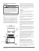
SHIPPING DAMAGE Upon receipt of equipment, the carton should be checked for external signs of shipping damage. The skid must remain attached to the unit until the unit is ready for installation. If damage is found, the receiving party must contact the last carrier immediately, preferably in writing, requesting inspection by the carrier’s agent. FIGURE 2 AIR SEAL UNDER QTEC UNIT UNIT REMOVAL FROM SKID WARNING This unit is heavy and requires more than one person to handle and remove from the skid.
HANDLING UNIT AFTER REMOVAL FROM SKID WARNING Exercise extreme caution when pushing the unit on the rollers. Handle and push from the lower 1/3 of the unit. Insure that debris is not on the floor where the unit is to be moved on the rollers. Failure to do so could result in the unit tipping over and causing bodily injury and/ or damage to the unit. The unit will have to be turned sideways and removed from the skid to fit through a 36" doorway.
FIGURE 5 INSTALLATION WITH FREE BLOW PLENUM FIGURE 6 DUCTED APPLICATION Manual Page 2100-519 9 of 42
DUCT WORK Any heat pump is more critical of proper operating charge and an adequate duct system than a straight air conditioning unit. All duct work must be properly sized for the design airflow requirement of the equipment. Air Conditioning Contractors of America (ACCA) is an excellent guide to proper sizing. All duct work or portions thereof not in the conditioned space should be properly insulated in order to both conserve energy and prevent condensation or moisture damage.
FRESH AIR INTAKE This unit is equipped with a fresh air damper assembly. The damper blade is locked in the closed position when the unit is shipped from the Factory. To allow the damper to operate remove the two plastic locking pins, one on each end of the blade. This will allow for maximum fresh airflow. The damper blade will now open when the indoor blower is operating. If less than maximum fresh airflow is required, reinsert the plastic pins to limit damper blade opening to desired level.
FIGURE 9 OPTIONAL SIDE DRAIN (SIDE VIEW) INSTALLATION FIGURE 10 STANDARD REAR DRAIN QTEC UNIT FIGURE 11 REAR DRAIN (TOP VIEW) DRAIN LINE WALL (MAXIMUM 10" FOR REAR DRAIN) SLEEVE COUPLINGS NOT SHOWN BUT RECOMMENDED FOR EASE OF REMOVABILITY FOR SERVICE.
Manual Page 2100-519 13 of 42 DRAIN BOX CAULK AROUND TUBE OVERFLOW TUBE WALL SLEEVE FIGURE 12A MIS-2469
FIGURE 12B PLUG INSTALLED IN SIDE Q/Tec DRAIN REAR DRAIN CONNECTION IN Q/Tec PRODUCT 3/4" PLASTIC PIPE NIPPLE SUPPLIED WITH DRAIN BOX KIT (APPLY TEFLON TAPE TO THREADS) IMPORTANT ! 1/2" SLIP X 1/2" SLIP X 3/4" NPT TEE SUPPLIED WITH DRAIN BOX KIT (TIGHTEN THREADS SO TEE IS HORIZONTAL TO FLOOR) MIS-2470 Manual 2100-519 Page 14 of 42
FIGURE 12C REMOVE KNOCK-OUT FOR INDOOR DRAIN HOSE CONNECTOR (If Used) MIS-2471 Manual Page 2100-519 15 of 42
FIGURE 12D DRAIN HOSE FROM INDOOR DRAIN PAN. MOVE HOSE FROM ATTACHMENT IN LOWER DRAIN PAN AND SLIDE ONTO DRAIN BOX BARB FITTING, SECURING WITH SUPPLIED CLAMP IF OUTDOOR PAN IS BYPASSED.
FIGURE 13A UNIT MOUNTING - METHOD 1 ENLARGED VIEW OF MOUNTING BRACKET SHOWING SLEEVE TO CABINET ATTACHMENT SIDE TRIM (2 PCS.) MOUNTING BRACKET QWS Series Wall Sleeve WALL SLEEVE SIDE TRIM (2 PCS.
INSTALLATION INSTRUCTIONS MOUNTING THE UNIT When installing a QTEC unit near an interior wall on the left side, a minimum of 8 inches is required; 12 inches is preferred. When installing a QTEC unit near an interior wall on the right side, a minimum of 18 inches is required as additional space is required to connect the side drain. If the rear condensate drain kit QCDS48 is used the minimum can be reduced to 8 inches.
WIRING – MAIN POWER Refer to the unit rating plate and/or Table 2 for wire sizing information and maximum fuse or “HACR Type” circuit breaker size. Each unit is marked with a “Minimum Circuit Ampacity”. This means that the field wiring used must be sized to carry that amount of current. Depending on the installed KW of electric heat, there may be two field power circuits required. If this is the case, the unit serial plate will so indicate. All models are suitable only for connection with copper wire.
LOW VOLTAGE CONNECTIONS These units use a grounded 24 volt AC low voltage circuit. The “R” terminal is the hot terminal and the “C” terminal is grounded. “G” terminal or pins 6 and 1 of P2 are the fan inputs. Both must be energized for proper fan operation. This is done automatically in the factory installed climate control options. If the climate control option is abandoned and connections are made directly to P2 both pins 6 and 1 of P2 must be energized for proper operation.
TABLE 4 WALL THERMOSTATS Thermostat Predominant Features 8403-060 (1120-445) 3 stage Cool; 3 stage Heat Programmable/Non-Programmable Electronic HP or Conventional Auto or Manual changeover 2 stage Cool; 2 stage Heat 8403-058 Electronic Non-Programmable (TH5220D1151) HP or Conventional Auto or Manual changeover 8403-056 Carbon Dioxide Sensor with LCD for (C7232A1008) Sensor Readings FIGURE 16 MIS-1285 Manual Page 2100-519 21 of 42
FIGURE 17A REMOTE THERMOSTAT WIRING DIAGRAM “X” THERMOSTAT OPTION REMOTE THERMOSTAT WIRING DIAGRAM "X" THERMOSTAT OPTION Thermostat #TH522001151 Bard Part #8403-058 Thermostat Bard Part #8403-060 Low Voltage Terminal Block G G G W1/E E E L L A O1 Plug #2 Orange Orange Red/Yellow Y1 Y Y Yellow O/B O/B B Blue W2 Aux W2 Brown R R R Red/White C Black/White 5 6 7 8 9 10 1 C C 2 3 4 Brown/White W1 Rc 1 W3 11 12 MIS-2687 1 Factory installed jumper.
FIGURE 17B REMOTE THERMOSTAT WIRING DIAGRAM “X” THERMOSTAT OPTION WITH DEMAND VENTILATION Optional CO2 Controller #C7232A1008 Bard Part #8403-056 Red 24VAC Black 1 Yellow Analog Out 3 Brown 5 2 4 Relay Part #8201-062 2 3 Orange Green Plug #2 G G G W1/E E E L L A O1 Orange Orange 1 2 3 Red/Yellow 4 Brown/White 5 6 W1 Y1 Y Y Yellow O/B O/B B Blue W2 Aux W2 Brown R Red/White C C Black/White Thermostat #TH522001151 Bard Part #8403-058 W3 R R Rc C Thermostat Bard
FIGURE 18 UNIT MOUNTED THERMOSTAT WIRING DIAGRAM “A” THERMOSTAT OPTION Plug #2 Temp. and Humidity Controller PART #8403-060 Orange 1 Brown/White 2 Red/Yellow 3 Purple 4 W1/E D/YO G Orange 5 6 Y1 7 8 9 R Yellow Blue Brown Red/White C Black/White O/B W2 10 11 12 4102-062 NOTE: On option X or A the CS2000A* (or other field provided means to control ventilation) must be used if any of the motorized ventilation options are installed.
FIGURE 19 UNIT MOUNTED THERMOSTAT WIRING DIAGRAM “D” THERMOSTAT OPTION Temp.
FIGURE 20 UNIT MOUNTED THERMOSTAT WIRING DIAGRAM “H” THERMOSTAT OPTION Red Analog Out Red/White Black Black/White 1 Yellow Brown Black/White Orange Green 3 5 2 4 Relay Part #8201-062 Brown/White 24VAC Red/White CO2 Controller Part #8403-056 Orange Orange Red/Yellow W1/E Plug #2 1 2 3 4 A G Temp.
START UP THESE UNITS REQUIRE R-410A REFRIGERANT AND POLYOL ESTER OIL. REMEMBER: When adding R-410A refrigerant, it must come out of the charging cylinder/tank as a liquid to avoid any fractionation, and to insure optimal system performance. Refer to instructions for the cylinder that is being utilized for proper method of liquid extraction. GENERAL: 1. Use separate service equipment to avoid cross contamination of oil and refrigerants. 2. Use recovery equipment rated for R-410A refrigerant. 3.
START UP DESCRIPTION OF STANDARD EQUIPMENT Solid State Electronic Heat Pump Control Provides efficient 30-minute defrost cycle. A thermistor sensor and speed up terminal for service along with a 10-minute defrost override are standard on the electronic heat pump control. High / Low Pressure Switch Provides refrigerant circuit high pressure and loss of charge protection. Includes lockout circuit that is resettable from room thermostat.
SERVICE HINTS 1. Caution user to maintain clean air filters at all times. Also, not to needlessly close off supply air registers. This may reduce airflow through the system, which shortens equipment service life as well as increasing operating costs and noise levels. 2. Switching to heating cycle at 75°F or higher outside temperature may cause a nuisance trip of the remote reset high pressure switch. Turn thermostat off, then on to reset the high pressure switch. 3.
VENT OPTIONS BAROMETRIC FRESH AIR DAMPER (Standard) Before starting, make sure the power has been turned off. The return air grille panel must be removed. The fresh air damper assembly can be seen on the back of the unit. See Figure 21. QTEC R ENERGY RECOVERY VENTILATOR (Option) Before starting, make sure that the power has been turned off. The return air grille panel must be removed. The energy recovery ventilator (QERV) can be seen after the panel has been removed.
FIGURE 21 FRESH AIR DAMPER REMOVAL MOUNTING SCREW Manual Page 2100-519 31 of 42
FIGURE 22 QERV REMOVAL POWER CONNECTORS MOUNTING SCREWS LOWER BLOWER ASSEMBLY POWER CONNECTOR FRONT FILL Manual 2100-519 Page 32 of 42
SEQUENCE OF OPERATION COOLING – Circuit R-Y makes at thermostat pulling in compressor contactor, starting the compressor and outdoor motor. The G (indoor motor) circuit is automatically completed on any call for cooling operation or can be energized by manual fan switch on subbase for constant air circulation. HEATING – A 24V solenoid coil on reversing valve controls heating cycle operation.
PRESSURE SERVICE PORTS High and low pressure service ports are installed on all units so that the system operating pressures can be observed. Pressure tables can be found later in the manual covering all models. It is imperative to match the correct pressure table to the unit by model number. Upper and lower service doors must be attached to obtain proper reading. DEFROST CYCLE The defrost cycle is controlled by temperature and time on the solid state heat pump control. See Figure 24.
FIGURE 24 DEFROST CONTROL BOARD LOW PRESSURE BYPASS TIMER SWITCH (FACTORY SETTING 120 SECONDS) SW SW 1 2 TIME (SEC) OFF OFF 30 ON OFF 60 OFF ON 120* ON ON 180 ACCUMULATED RUN TIME SELECTOR (FACTORY SETTING 30 MIN.
TROUBLESHOOTING SOLID STATE HEAT PUMP CONTROL TROUBLESHOOTING PROCEDURE 1. NOTE: A thorough understanding of the defrost cycle sequence is essential. Review that section earlier in this manual prior to troubleshooting the control. Turn on AC power supply to unit. 2. Turn thermostat blower switch to “fan on” – the indoor blower should start. (If it doesn’t, troubleshoot indoor unit and correct problem.) 3. Turn thermostat blower to “auto” position. Indoor blower should stop.
CHECKING TEMPERATURE SENSOR 4. If sensor resistance reads very low, then sensor is shorted and will not allow proper operation of the heat pump control. 1. Disconnect temperature sensor from board and from outdoor coil. 5. If sensor is out of tolerance, shorted, open, or reads very low ohms then it should be replaced. 2. Use an ohmmeter and measure the resistance of the sensor. Also use ohmmeter to check for short or open. 3.
TROUBLESHOOTING GE ECM™ MOTORS CAUTION: Disconnect power from unit before removing or replacing connectors, or servicing motor. To avoid electric shock from the motor’s capacitors, disconnect power and wait at least 5 minutes before opening motor. Symptom Cause/Procedure • Noisy blower or cabinet • Check for loose blower housing, panels, etc.
TROUBLESHOOTING GE ECM™ MOTORS CONT’D. Replacing ECM Control Module To replace the control module for the GE variable-speed indoor blower motor you need to take the following steps: 1. You MUST have the correct replacement module. The controls are factory programmed for specific operating modes. Even though they look alike, different modules may have completely different functionality. USING THE WRONG CONTROL MODULE VOIDS ALL PRODUCT WARRANTIES AND MAY PRODUCE UNEXPECTED RESULTS. 2.
FAN BLADE SETTING DIMENSIONS REFRIGERANT CHARGE Any service work requiring removal or adjustment in the fan and/or motor area will require that the dimensions in Table 7 be checked and blade adjusted in or out of the motor shaft accordingly. The correct system R-410A charge is shown on the unit rating plate. Optimum unit cooling performance will occur with a refrigerant charge resulting in a Super Heat (with orifice) or with Subcooling (with TXV) as shown in Tables 8 and 8A.
TABLE 10 COOLING PRESSURE (ALL TEMPERATURES IN DEGREES F) MODEL Q24H1 Q30H1 Q36H1 Q42H1 Q48H1 Q60H1 R E TU R N AIR TEMP.
TABLE 11 HEATING PRESSURE (ALL TEMPERATURES IN DEGREES F) MODEL R E TU R N AIR TEMP.