
Manual


Manual 2100-519
Page 40 of 42
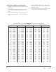
FAN BLADE SETTING DIMENSIONS
Any service work requiring removal or adjustment in
the fan and/or motor area will require that the
dimensions in Table 7 be checked and blade adjusted in
or out of the motor shaft accordingly.
1 Maximum ESP (inches WC) shown is with 1" thick disposable filter (reduced by .2 for 2" filter).
2 Rated CFM for ducted applications – required for maximum performance rating. To obtain full CFM on models Q36H1, Q42H1,
Q48H1 and Q60H1 connect the pink jumper wire (provided) to terminal #G2 and #Y on the low voltage terminal block located in
the circuit breaker box.
3 Optional CFM – the unit is shipped from the factory set to operate at the optional CFM level shown. This provides lower
operating sound levels for non-ducted, free discharge applications. This reduces system capacity performance by approximately
2% at the same energy efficiency.
4 Continuous fan CFM is the total air being circulated during continuous fan mode.
5 Model Q24H1 – when operating on 2nd stage heating the indoor air will increase to 1000 CFM.
REFRIGERANT CHARGE
The correct system R-410A charge is shown on the unit
rating plate. Optimum unit cooling performance will
occur with a refrigerant charge resulting in a Super Heat
(with orifice) or with Subcooling (with TXV) as shown
in Tables 8 and 8A. If correct charge is in doubt,
recover the refrigerant and recharge per the charge on
the unit rating plate.
LEDOM
ANOISNEMID
)SEHCNI(
1H42Q
1H03Q
1H63Q
1H24Q
1H84Q
1H06Q
057.
057.
057.
057.
057.
057.
TABLE 8
SUPER HEAT AT COMPRESSOR
ledoM
detaR
MFC
DO°59
erutarepmeT
DO°28
erutarepmeT
1H42Q00881-6161-41
1H03Q000102-8181-61
1H24Q002112-9181-61
1H84Q004152-3242-22
1H06Q05519-751-31
NOTE: These units are equipped with a variable speed (ECM) indoor motor that automatically adjust itself to
maintain approximately the same rate of indoor airflow in both heating and cooling, dry and wet coil
conditions and at both 230/208 or 460 volts.
TABLE 9
INDOOR BLOWER PERFORMANCE
ledoM
PSEdetaR
1
PSE.xaM
2
MFCdetaR
3
lanoitpO
MFC
4
suounitnoC
MFC
@MFC
xaM
PSE.
1H42Q
5
01.5.0008008007
1H03Q51.8.000010001019
1H63Q51.8.00021000100015711
1H24Q51.8.00021000100015711
1H84Q51.8.00041001100115711
1H06Q02.5.00551052105210041
FIGURE 28
FAN BLADE SETTING
TABLE 7
FAN BLADE DIMENSIONS
TABLE 8A
SUBCOOLING AT LIQUID LINE
ledoM
detaR
MFC
DO°59
erutarepmeT
DO°28
erutarepmeT
1H63Q002131-1101-8