INSTALLATION INSTRUCTIONS Commercial Room Ventilator with Exhaust, Multi-Step and Optional CO2/2-10V Modulating Control Model: QWSCRV (920-0538) For Use with Bard QW*S Series Geothermal 2-Stage Heat Pumps Bard Manufacturing Company, Inc. Bryan, Ohio 43506 www.bardhvac.
CONTENTS Description .............................................................3 Blade Adjustment for Desired Ventilation Air ..............4 "V" Option CRV Sequence of Operation ......................7 Manual 2100-763B Page 2 of 10 Figures Figure 1 Figure 2 Figure 3 Figure 4 CRV Installation and Adjustment ............ 3 CRV Control Board ................................ 7 8403-096 CO2 Sensor Set Up ................ 9 CRV Wiring Diagram ............................
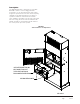
Description The QWSCRV ventilator is designed to be used with Bard QW*S Q-TECTM series 2-stage geothermal heat pumps. It is an electromechanical vent system designed to provide fresh air to meet indoor air quality standards. It automatically adjusts to the mode of operation to maintain consistent fresh air intake levels. Examples are blower only, part load cooling and full load cooling, which are all set for different total airflows.
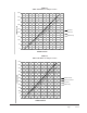
Blade Adjustment for Desired Ventilator Air interior of the sheet metal damper assembly per the graph. The amount of ventilation air supplied by the commercial room ventilator is dependent on five (5) factors: 2. Set the damper position for part load (stage 1) cooling or heating operation. A.
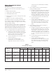
GRAPH 1 QW2S CRV Airflow vs. Damper Position 450 400 350 FRESH AIR CFM 300 250 Full Load 200 Part Load Blower Only 150 100 50 0 5 10 15 20 25 30 DAMPER POSITION GRAPH 2 QW3S CRV Airflow vs.
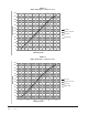
GRAPH 3 QW4S CRV Airflow vs. Damper Position 600 550 500 450 FRESH AIR CFM 400 350 Full Load 300 Optional Full Load 250 Part Load 200 Blower Only 150 100 50 0 5 10 15 20 25 30 DAMPER POSITION GRAPH 4 QW5S CRV Airflow vs.
"V" Option CRV Sequence of Operation “Y1” Potentiometer setting: This potentiometer can be used to adjust the blade setting for outdoor air intake when the “Y1” terminal is energized on the low voltage terminal strip indicating 1st stage cooling or Balanced Climate operation. When energized, it overrides the “OCC” potentiometer setting. The “V” Ventilation option includes a control board with blade positioning potentiometers along with an input for a 2-10V input signal (see Figure 2).
plug in the unit control panel. All potentiometers must be set to the off position and the PP jumper must be in the "0" position for total modulation. The OCC potentiometer can be used to maintain a minimum blade position when "A" is energized. Refer to Figure 3 for more information on Bard CO2 sensor part #8403-096 set up. • Method 2: The damper motor will accept a 2-10VDC signal with a resistive load less than 5000 ohms.
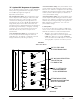
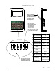
FIGURE 3 8403-096 CO2 Sensor Set Up PRESS UP AND DOWN ARROWS TO ENTER CONFIGURATION MODE USE ARROWS TO SELECT SETTING. PUSH MIDDLE BUTTON TO CHANGE. CONTROLLER WILL SHOW SET. NOTE: MENU DIP SWITCH MUST BE IN "ON" POSITION #5 TO CHANGE ANY SETTINGS WITH THE SIDE BUTTONS. TO LOCK THE CO2 CONTROLLER MOVE DIP SWITCH TO "OFF" AFTER IT HAS BEEN CONFIGURED.
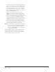
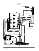
FIGURE 4 CRV Wiring Diagram UNIT LOW -VOLT TERMINAL STRIP A CO2 (8403-096) R C 1 *B *A 2 3 4 CRV CONTROL BOARD 2 5 R7 *B 1 W2 Y 26 ACTUATOR COM BLACK RED W2 Y R1 24 6 PURPLE 24V 25 W2 Y WHITE R2 Control FDBK R3 90 60 30 0 BROWN/WHITE YELLOW PURPLE GRAY RED/WHITE BROWN/WHITE *Unused - Tape off 22 RELAY NC NO BLACK/WHITE BLACK/WHITE COM BLUE BLUE BROWN/WHITE RED/WHITE Manual 2100-763B Page 10 of 10 1 2 3 4 5 6 7 8 9 10 11 12 4114-107 C VENT PLUG 3