WG - SERIES COMBINATION GAS/ELECTRIC WALL-MOUNT INSTALLATION INSTRUCTIONS MODELS: W24G1-A W36G1-B W48G1-C W24G1-B W36G1-C W60G1-A W24G1-C W42G1-A W60G1-B W30G1-A W42G1-B W60G1-C W30G1-B W42G1-C W30G1-C W48G1-A W36G1-A W48G1-B WARNING READ ALL INSTRUCTIONS CAREFULLY BEFORE BEGINNING THE INSTALLATION. THE INSTALLATION MUST COMPLY WITH THESE INSTRUCTIONS AND THE REQUIREMENTS OF ALL GOVERNING CODES AND ORDINANCES FOR THE INSTALLATION LOCATION.
CONTENTS Page Page Getting Other Information and Publications .............. 4 W**G Series Model Nomenclature ............................ 5 Ventilation Options .................................................... 5 Air Conditioning Module Options ............................... 6 1. Important ............................................................ 6 2. Application .......................................................... 6 3. Duct Work .................................................. 6 & 10 4.
CONTENTS Page FIGURES Figure 1 Figure 2 Figure 2A Figure 3 Figure 3A Figure 4 Figure 5 Figure 6 Figure 7 Figure 8 Figure 9 Figure 10 Figure 11 Figure 12 Figure 13 Figure 14 Figure 15 Figure 16 Figure 17 Figure 18 Figure 19 Figure 20 Figure 21 Figure 22 Unit Dimensions ..................................... 9 Mounting Instructions – W24-36G ....... 12 Mounting Instructions – W42-60G ....... 13 Combustible Clearance – W24-36G .... 14 Combustible Clearance – W42-60G .... 14 Wall Mounting Instructions .........
Getting Other Information and Publications These publications can help you install the furnace. You can usually find these at your local library or purchase them directly from the publisher. Be sure to consult current edition of each standard.
WALL MOUNT GAS/ELECTRIC GENERAL MODEL NUMBER NOMENCLATURE W 42 MODEL G 1 – A X C REVISION COOLING CAPACITY 24 = 2 ton 30 = 2½ ton 36 = 3 ton 42 = 3½ ton 48 = 4 ton 60 = 5 ton X VOLTAGE A = 230/208-60-1 B = 230/208-60-3 C = 460-60-3 FEATURE (-) = Standard D = Dehumidification C = Canadian Approval EMISSIONS X = Standard N = NOx Certified X X X COLOR X = Beige (Standard) 4 = Gray VENT (See Table Below) Wall Mount GAS/ ELECTRIC X FILTER X = 2" Pleated (Standard) W = 1" Washable X CONTR
AIR CONDITIONING MODULE OPTIONS 1 CCM 2 H PC 3 LP C 4 LAC STD STD STD 5 SK Factory Installed C ode Field Installed Part H CMA-28 Field Only SK111 or CMC-15 STD = Standard equipment. 1 CCM Compressor control module has adjustable 30 second to 5 minute delay-on-break timer. On initial power up, or any time the power is interrupted, the delay-on-make will be 2 minutes plus 10% of the delay-on-break setting. There is no delay-on-make during routine operation of the unit.
Manual Page 2100-525 7 of 73 1/5 2.2 230/208-60-1 1/4 2400 1.8 230/208-60-1 1.5 * 75 degree C Copper wire size ** Maximum time delay fuse or HACR Type circuit breaker Full Load Amps Volts Horsepower Blower M otor C FM Full Load Amps Volts Horsepower Fan M otor Full Load Amps (3-motors) Volts 58 8.3 6.4/7.1 230/208-3 25 16 230/208-60-1 64 Energy Recovery Ventilator 12.8 Lock Rotor Amps 9.9/10.
Manual 2100-525 Page 8 of 73 1/3 2.2 230/208-60-1 1/3 3050 3.4 230/208-60-1 2.5 * 75 degree C Copper wire size ** Maximum time delay fuse or HACR Type circuit breaker Full Load Amps Volts Horsepower Blower M otor C FM Full Load Amps Volts Horsepower Fan M otor Full Load Amps (3-motors) Volts 83.1 13.1 10.2/11.5 230/208-3 35 23 197-253 230/208-60-1 109 Energy Recovery Ventilator 19.9 Branch Circuit Selection Current 15.5/17.
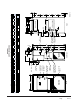
Manual Page 2100-525 9 of 73 G F FRONT CONDENSER AIR OUTLET U 2.88 3.88 C 13.88 15.88 CONTROL PANEL DOOR SERVICE/FILTER HINGED DOOR COMBUSTION AIR INTAKE COMBUSTION AIR EXHAUST VESTIBULE DOOR N V 22.9 24.9 D 24.25 27.25 4 DEG. PITCH IN TOP 3.75 T B 27.88 29.88 VENT OPTION PANEL CIRCUIT BREAKER/ DISCONNECT ACCESS PANEL (LOCKABLE) S 12 - 7 HOLES 16 - 6 HOLES UNIT W24G-W30G-W36G W42G-W48G-W60G W A 7.88 9.88 UNIT W24G-W30G-W36G W42G-W48G-W60G P W 38 42 DD Y 4.44 8.
4. HIGH ALTITUDE APPLICATIONS WARNING In all cases, there must be a metal duct connection made to the supply air flange, and a one inch clearance to combustibles must be maintained to this duct connection. For free blow applications, a metal sleeve must be used in the wall opening itself, again maintaining a one inch clearance to combustibles. Failure to use the sheet metal can cause fire resulting in property damage, injury, or death.
7. WALL MOUNTING INFORMATION 1. Two holes for the supply and return air openings must be cut through the wall as detailed in Figure 4. 2. On wood-frame walls, the wall construction must be strong and rigid enough to carry the weight of the unit without transmitting any unit vibration. 3. Concrete block walls must be thoroughly inspected to insure that they are capable of carrying the weight of the installed unit.
Manual 2100-525 Page 12 of 73 12" 4 11/16" 29 3/4" 39 3/16" UNIT SUPPORT 5 9/16" Ø2 3/4" HIGH VOLTAGE (OPTIONAL) 2 15/16" 12" 12" RETURN AIR DUCT 12" Ø2" LOW VOLTAGE (OPTIONAL) Ø2 3/4" GAS OPENING (OPTIONAL) SUPPLY AIR DUCT 4 9/16" 30" 2" 8 5/8" (12) FLANGE SCREWS 29" 5 1/16" 12" 12" 4 9/16" OUTSIDE WALL WITH UNIT REMOVED 2 1/4" 7/16" 4 1/2" 2 15/16" 2 1/4" FOAM AIR SEAL TOP 27" CONTROL 15" PANEL 28 5/16" 10" VESTIBULE DOOR WALL STRUCTURE (OUTSIDE) 1" MIN.
Manual Page 2100-525 13 of 73 FIGURE 2A MOUNTING INSTRUCTIONS FOR W42G, W48G AND W60G
FIGURE 3 COMBUSTIBLE CLEARANCE FOR W24G, W30G AND W36G MODELS FIGURE 3A COMBUSTIBLE CLEARANCE FOR W42G, W48G AND W60G MODELS WARNING A minimum of one (1) inch clearance must be maintained between the supply air duct and combustible materials. This is required for the first three (3) feet of ducting. It is important to insure that the one (1) inch minimum spacing is maintained at all points.
FIGURE 4 WALL MOUNTING INSTRUCTIONS FIGURE 5 WALL MOUNTING INSTRUCTIONS Manual Page 2100-525 15 of 73
FIGURE 6 COMMON WALL MOUNTING INSTALLATIONS Manual 2100-525 Page 16 of 73
TABLE 2 MINIMUM INSTALLATION CLEARANCES 9. CLEARANCES Minimum clearances, as specified in Table 2, must be maintained from adjacent structures to provide adequate fire protection, adequate combustion air, and room for service personnel. While minimum clearances are acceptable for safety reasons, they may not allow adequate air circulation around the unit for proper operation in the cooling mode.
10. VENT TERMINAL AND COMBUSTION AIR INLET HOOD The vent terminal is shipped in the burner compartment. See Figure 7. Remove the two shipping screws and separate the two-piece assembly. Install the vent terminal by using the four screws provided. Do not cut or trim gasket. Make sure gasket is in place. See Figure 8. The combustion air intake hood is factory installed. 11. OPTIONAL VERTICAL VENTING With the optional vertical venting kit (VVK-5) this unit may be vented vertically through a roof or overhang.
12. VENT RESIZING INSTRUCTIONS 13. FRESH AIR INTAKE When an existing furnace is removed from a venting system servicing other appliances, the venting system is likely to be too large to properly vent the remaining attached appliances. All units are built with fresh air inlet slots punched in the service panel.
15. WIRING – MAIN POWER WARNING For your personal safety, turn off electric power at service entrance panel before making any electrical connections. Failure to do so could result in electric shock or fire. Refer to unit rating plate for wire sizing information and maximum fuse or “HACR” type circuit breaker size. Each outdoor unit is marked with a “Minimum Circuit Ampacity”. This means that the field wiring used must be sized to carry that amount of current.
FIGURE 10 INSTALLATION OF FLEXIBLE CONDUIT 16. WIRING – LOW VOLTAGE WIRING Low Voltage Connection These units use a 24-volt AC low voltage circuit. The “R” terminal is the hot terminal and the “C” terminal is grounded. “G” terminal is the fan input. “Y1” terminal is the compressor input. “R” terminal is 24 VAC hot. “C” terminal is 24 VAC grounded. “A” terminal is the ventilation input. This terminal energizes any factory or field installed vent option. “W1” terminal is the heat input.
FIGURE 11 LOW VOLTAGE WIRING Low Voltage Wiring - No Ventilation Package Thermostat Subbase Thermostat Part #8403-057 TH3110D1040 C W Thermostat Part #8403-060 (1120-445) C W1/E A R W2 D/YO C W1 A R W2 E 1 R B Y G Y2 Y1 G O/B Y2 Y1 G 1 RC O 2 Unit 24V Terminal Block Y L 3 2 F Factory Installed Jumper Unit Control Panel 1 SET SWITCH ON THERMOSTAT TO "GAS-OIL" 2 CONFIGURE THERMOSTAT FOR HEAT/COOL MIS-2774 Manual 2100-525 Page 22 of 73
FIGURE 12 LOW VOLTAGE WIRING Low Voltage Wiring - MOTORIZED FRESH AIR DAMPER, COMMERCIAL ROOM VENTILATOR-SPRING, COMMERCIAL ROOM VENTILATOR-POWER Thermostat Subbase Thermostat Part #8403-057 (TH311DD1040) 1 Thermostat Part #8403-060 (1120-445) 2 RC C W R C W1/E A R W2 D/YO C W1 A R W2 E Y G B Y2 Y1 G O/B Y2 Y1 G 1 O L (MUST BE CONFIGURED FOR HEAT/COOL) Unit 24V Terminal Block Factory Installed Jumper 4 Y 3 2 F 3 ORANGE RED/WHITE BROWN/WHITE BLUE BLACK/WHITE U
FIGURE 13 LOW VOLTAGE WIRING Low Voltage Wiring - EIFM ECONOMIZER Thermostat Part #8403-058 (TH5220D1151) 1 Thermostat Part #8403-060 (1120-445) 1 Unit 24V Terminal Block C W C W1/E C W1 Thermostat Subbase R W2 RC Y2 Y G A R W2 D/YO Y2 Y1 G O/B A R W2 E Y2 Y1 G 1 Y L 3 2 F Factory Installed Jumper Unit Control Panel WGSEIFM-5 WIRES FROM PLUG BLACK BLUE PINK YELLOW PURPLE ORANGE RED RED THERMISTOR MIS-2777 1 Manual 2100-525 Page 24 of 73 CONFIGURE THERMOSTAT FOR
FIGURE 14 GAS PIPE CONNECTION W24G - W36G W42G - W60G Manual Page 2100-525 25 of 73
18. GAS SUPPLY AND PIPING GENERAL RECOMMENDATIONS 1. Be sure the gas line complies with the local codes and ordinances, or in their absence with the National Fuel Gas Code, ANSI Z223.1, or Natural Gas Installation Code, CAN/CGA B149.1, or Propane Installation Code B149.2, latest edition. 2. A sediment trap or drip leg must be installed in the supply line to the furnace. 3.
PROPANE (LP) GAS CONVERSION This unit may be converted in the field for use with Propane (LP) gas. Propane gas conversion kit number WGCK-1 is designed for conversions of units installed from 0 – 6,000 feet elevations. Propane gas conversion kit number WGCK-2 is designed for conversions of units installed from 6,001 – 10,000 feet elevations. These kits may be purchased from your local distributor.
NATURAL GAS INPUT RATE Natural gas heating value (BTU/cu. ft.) can vary significantly. Before starting natural gas input check, obtain gas heating value at your location from local supplier. You will need a stopwatch to measure actual gas input. 9. If you left water heater, dryer or range pilots on, allow for them in calculating correct furnace gas input. A quick way is to allow 1,000 BTU per hour for a water heater, 500 BTU per hour for dryer and 500 BTU per hour for each range burner pilot. Example: 1.
21. STANDARD ORIFICE SIZING AND HIGH ALTITUDE DERATE This furnace is shipped with fixed gas orifices for use with Natural Gas and sized for 1000 BTU/cubic foot gas. Make sure actual gas input does not exceed rating plate input. You may need to change orifices to get correct gas input. Whether you do or not depends on input, and your gas heat value at standard conditions and elevation. Consult your local gas supplier for gas heat value and any special derating requirements.
TABLE 8 NATURAL GAS ORIFICE TABLES FOR MODELS W24G, W30G AND W36G Factory Standard Input Gas Heat* Value BTU/Cu. Ft. Up to 6,000 Feet No C h an g es E xcep t for BTU Content 6,001 to 8,000 Feet Requires Pressure Sw itch Change and Orifice Change Based on BTU Contentt 8,001 to 10,000 Feet Requires Pressure Sw itch Change and Orifice Change Based on BTU Contentt 700-749 2.75 2.70 2.60 750-799 2.70 2.60 2.50 800-849 2.60 2.50 2.45 850-899 2.50 2.45 2.35 900-949 2.45 2.35 (2.
TABLE 8A NATURAL GAS ORIFICE TABLES FOR MODELS W42G, W48G AND W60G Factory Standard Input Gas Heat* Value BTU/Cu. Ft. Up to 6,000 Feet No C h an g es E xcep t for BTU Content 6,001 to 8,000 Feet Requires Pressure Sw itch Change and Orifice C h an g e Based on BTU Contentt 25000 B T U Per Burner 700-749 2.90 2.80 2.70 750-799 2.80 2.70 2.60 800-849 2.70 2.60 2.50 850-899 2.60 2.50 2.45 900-949 2.50 2.45 (2.40) 950-999 2.45 (2.40) 2.35 1000-1049** (2.40) 2.35 [2.
22. CONVERSION OF GAS INPUT BTUH FROM HIGH TO LOW RATING All the derated WG series units are produced with maximum BTUH input orifices installed. To field convert input, a change to main burner orifices is required. NOTE: No change to air orifices is necessary. A set of low input orifices is shipped with every unit. They will be found packaged in a bag behind the burner door. Refer to the unit rating plate to confirm the proper orifice size. Proper installation of the orifices is detailed as follows: A.
FIGURE 16 ACCESS INTERNAL FILTER THROUGH UPPER SERVICE DOOR 24. FILTERS A 2" thick throwaway filter is supplied with each unit. This filter is installed by opening the main service door. (See Figure 16.) Replacement filters are available through your dealer. 25. COMPRESSOR CONTROL MODULE The compressor control is an anti-short cycle/lockout timer with high and low pressure switch monitoring and alarm output.
ALARM OUTPUT PHASE MONITOR Alarm terminal is output connection for applications where alarm signal is desired. This terminal is powered whenever compressor is locked out due to HPC or LPC sequences as described. All units with three phase scroll compressors are equipped with a three phase line monitor to prevent compressor damage due to phase reversal. NOTE: Both high and low pressure switch controls are inherently automatic reset devices.
26.
27. SERVICE AGENCY PROCEDURES FIGURE 18 TOP VIEW OF GAS CONTROL CAUTION Label all wires prior to disconnection when servicing controls. Wiring errors can cause improper and dangerous operation. Verify proper operation after servicing. WARNING Follow these procedures before inspecting furnace. • Turn room thermostat to its lowest or off setting. • Turn off manual gas shut off valve. • Wait at least 5 minutes for furnace to cool if it was recently operating.
WARNING Disconnect electrical power before servicing unit. Failure to do so could result in electrical shock or death. ROUTINE MAINTENANCE 1. Air Filters – Check the condition at least monthly when the unit is in use, and replace as necessary. 2. Lubrication Requirements – The indoor circulating air blower motor and outdoor circulating air fan motor are permanently lubricated and requires no reoiling. The combustion air blower motor requires no re-oiling.
30. SEQUENCE OF OPERATION – HEATING On a call for heat from the thermostat, the induced draft blower is energized. Once sufficient draft is established, the pressure switch contacts close and the ignition system is energized. The direct spark ignitor will be energized allowing gas to flow. At the same time the main valve is energized, a 30-second blower delay timer is activated. After this delay, the heating speed blower relay energizes.
FIGURE 20 FURNACE CONTROL BOARD AND BLOWER CONTROL 32. INDOOR BLOWER OPERATION All models have multiple speed direct drive blower motors. If supply and return ducts are connected to the unit, the ducts must be of adequate size. Refer to the appropriate blower tables. See Tables 10, 11, 12, 13, 14 and 15 for maximum static pressures acceptable. Note the minimum CFM for cooling operation.
TABLE 10 W24G INDOOR BLOWER PERFORMANCE @ 230 AND 460 VOLTS Recommended W24G cooling airflow range at rated 800 CFM @ 0.15 ESP (WC) is 680 - 920 CFM Factory set on Low Speed for cooling and High for heating. COOLING MODE ESP Inches H 2O MANUAL FAN and HEATING MODE Wet Coil High Medium 90,000 BTU Input Low High Medium 81,000 BTU Input Low High Medium Low 0.0 --- --- 890 1350 1120 --- --- 1120 940 0.1 --- --- 820 1260 1060 --- --- 1060 870 0.
TABLE 11 W30G INDOOR BLOWER PERFORMANCE @ 230 AND 460 VOLTS Recommended W30G cooling airflow range at rated 1000 CFM @ 0.35 ESP (WC) is 820 - 1150 CFM Factory set on Medium Speed for cooling and for heating. COOLING MODE MANUAL FAN and HEATING MODE ESP Inches H 2O High Medium Low High Medium Low High Medium Low 0.0 --- --- 1060 --- 1350 1120 --- 1350 1120 0.1 --- --- 1000 --- 1260 1060 --- 1260 1060 Wet Coil 90,000 BTU Input 81,000 BTU Input 0.
TABLE 12 W36G INDOOR BLOWER PERFORMANCE @ 230 AND 460 VOLTS Recommended W36G cooling airflow range at rated 1100 CFM @ 0.250 ESP (WC) is 935 - 1265 CFM Factory set on Medium Speed for cooling and for heating. COOLING MODE ESP Inches H 2O Wet Coil High Medium MANUAL FAN and HEATING MODE 90,000 BTU Input Low High Medium Low 81,000 BTU Input High Medium Low 0.0 --- --- 1060 --- 1350 1120 --- 1350 1120 0.1 --- 1220 1000 --- 1260 1060 --- 1260 1060 1010 0.
TABLE 13 W42G INDOOR BLOWER PERFORMANCE @ 230 AND 460 VOLTS Recommended W42G cooling airflow range at rated 1300 CFM @ .35 ESP (WC) is 1500 - 1030 CFM Factory set on Medium Speed for heating and cooling COOLING MODE MANUAL FAN and HEATING MODE ESP Inches H sO High Medium Low High Medium Low High Medium Low .00 --- 1540 1140 --- 1640 1230 --- 1640 1230 .10 --- 1480 1090 --- 1580 1180 --- 1580 1180 .20 --- 1410 1030 1880 1510 --- --- 1510 1090 .
TABLE 14 W48G INDOOR BLOWER PERFORMANCE @ 230 AND 460 VOLTS Recommended W48G cooling airflow range at rated 1550 CFM @ .38 ESP (WC) is 1750 - 1280 CFM Factory set on High Speed for cooling and Medium Speed for heating. COOLING MODE MANUAL FAN and HEATING MODE ESP Inches H sO High Medium Low High Medium Low High Medium Low .00 --- 1540 --- --- 1640 1230 --- 1640 1230 .10 --- 1480 --- --- 1580 1180 --- 1580 1180 .20 1780 1410 --- 1880 1510 --- --- 1510 1110 .
TABLE 15 W60G INDOOR BLOWER PERFORMANCE @ 230 AND 460 VOLTS Recommended W60G cooling airflow range at rated 1650 CFM @ .30 ESP (WC) is 1910 - 1340 CFM Factory set on High Speed for cooling and Medium Speed for heating. COOLING MODE MANUAL FAN and HEATING MODE ESP Inches H sO High Medium Low High Medium Low High Medium Low .00 1930 1540 --- --- 1640 1230 --- 1640 1230 .10 1850 1480 --- --- 1580 1180 --- 1580 1180 .20 1780 1410 --- 1880 1510 --- --- 1510 1110 .
TABLE 16 INTEGRATED FURNACE AND BLOWER CONTROL OPERATION IGNITION SEQUENCE CONTROL Ignition Source 24 VAC DSI Flame Sensing Remote Timings - Prepurge Postpurge Inter-trial purge Pressure switch proving period Trials for ignition Trial for ignition Ignition sequence lockout seconds seconds (0 if cycle terminated before valve "on") seconds seconds per ignition sequence seconds total time to prove flame minutes (after 3 trials for ignition), auto reset can be reset during the 60 minute lockout period by
33. PRESSURE SERVICE PORTS High and low pressure service ports are installed on all units so that the system operating pressures can be observed. Tables 17A & 17B outlines expected pressures at various indoor and outdoor temperatures. TABLE 17A COOLING PRESSURE TABLE Model W24G1 W30G1 W36G1 Return Air Temperature Pressure 60° 65° 70° 75° 80° 85° 75 deg. D B 62 deg. WB Low S i de High Side 105 227 108 250 111 115 273 296 118 319 121 124 342 364 90° 80 deg. D B 67 deg.
34. REFRIGERANT CHARGE The correct system R-410A charge is shown on the unit rating plate. Optimum unit performance will occur with a refrigerant charge resulting in a suction line temperature (6" from compressor) as shown in Table 18. The suction line temperatures in Table 18 are based upon 80 degrees F dry bulb / 67 degree wet bulb (50% R.H.) temperature and rated airflow across the evaporator during cooling cycle. If charge quantity is in doubt, reclaim and recharge to factory name plate quantity.
INDEX WIRING DIAGRAMS and LADDER DIAGRAMS Unit Model No. Basic Wiring Diagram Manual P ag e N o . Basic Ladder Diagram Manual P ag e N o .
Indoor Fan Capacitor Evaporator Section BLOWER SPEED COLOR CODE Indoor Fan Motor Brown Brown HIGH MEDIUM LOW BLACK BLUE RED INTEGRATED FURNACE CONTROL 13 RED LOW VOLTAGE STRIP 11 BLUE BLACK 32 34 YELLOW PRIMARY LIMIT 32 BROWN RED 32 YELLOW RED/WHITE SECONDARY LIMIT 32 32 RED 32 ORANGE FUSE PINK 33 GRAY SPARK IGNITOR P3 10 11 12 7 8 9 4 5 6 BLUE BLACK 32 RED 32 32 39 38 RED 42 BLACK/WHITE 18 MOVE RED WIRE TO 208V TAP FOR 208V OPERATION BLACK 20 T1 YELLOW/RED BLACK/WHITE
W24G1-A 230/208-60-1 Manual Page 2100-525 51 of 73
Indoor Fan Capacitor Evaporator Section BLOWER SPEED COLOR CODE Indoor Fan Motor Brown Brown HIGH MEDIUM LOW BLACK BLUE RED INTEGRATED FURNACE CONTROL 13 RED LOW VOLTAGE STRIP 11 BLACK BLUE 32 34 YELLOW PRIMARY LIMIT 32 BROWN RED 32 YELLOW RED/WHITE SECONDARY LIMIT 32 32 RED 32 ORANGE FUSE PINK 33 10 11 12 7 8 9 4 5 6 SPARK IGNITOR P3 BLUE BLACK 135 120 150 32 BLACK BLUE C 59 BLACK FLAME SENSOR 35 2 3 1 SPEED NO PRESSURE SWITCH BLUE 32 MV PURPLE L1 41 38 32
W24G1-B 230/208-60-3 Manual Page 2100-525 53 of 73
Indoor Fan Capacitor Evaporator Section Brown Brown LOW VOLTAGE STRIP 11 YELLOW RED BLACK 32 INTEGRATED FURNACE CONTROL 13 BLUE ORANGE PURPLE PRIMARY LIMIT 34 BLOWER SPEED COLOR CODE HIGH BLACK MEDIUM BLUE LOW RED AUX PURPLE/ORANGE Indoor Fan Motor 32 BROWN RED 32 YELLOW RED/WHITE SECONDARY LIMIT 32 32 RED 32 ORANGE FUSE 33 10 11 12 7 8 9 4 5 6 C BLUE 135 120 150 SPEED 59 BLACK 35 2 3 1 FLAME SENSOR 28 47 58 57 32 3 RED BLUE 3 LOW SPEED BLOWER RELAY 57 49 R
W24G1-C 460-60-3 Manual Page 2100-525 55 of 73
Indoor Fan Capacitor Evaporator Section BLOWER SPEED COLOR CODE Indoor Fan Motor Brown Brown HIGH MEDIUM LOW BLACK BLUE RED INTEGRATED FURNACE CONTROL 13 BLACK LOW VOLTAGE STRIP 11 RED BLUE 32 34 YELLOW PRIMARY LIMIT 32 BROWN RED 32 YELLOW RED/WHITE SECONDARY LIMIT 32 32 RED 32 ORANGE FUSE PINK 33 GRAY SPARK IGNITOR P3 10 11 12 7 8 9 4 5 6 RED BLUE 120 32 BLACK 32 32 39 38 RED 42 BLACK/WHITE 18 MOVE RED WIRE TO 208V TAP FOR 208V OPERATION BLACK 20 T1 YELLOW/RED BLACK/W
W30G1-A, W36G1-A 230/208-60-1 Manual Page 2100-525 57 of 73
Indoor Fan Capacitor Evaporator Section BLOWER SPEED COLOR CODE Indoor Fan Motor Brown Brown HIGH MEDIUM LOW BLACK BLUE RED INTEGRATED FURNACE CONTROL 13 BLACK LOW VOLTAGE STRIP 11 BLUE RED 32 34 YELLOW PRIMARY LIMIT 32 BROWN RED 32 YELLOW RED/WHITE SECONDARY LIMIT 32 32 RED 32 ORANGE FUSE PINK 33 10 11 12 7 8 9 4 5 6 SPARK IGNITOR P3 NO BLACK 135 120 150 PRESSURE SWITCH BLUE 52 32 BLACK BLUE C 59 BLACK FLAME SENSOR 35 2 3 1 SPEED 32 MV PURPLE L1 41 38 32 L
W30G1-B, W36G1-B 230/208-60-3 Manual Page 2100-525 59 of 73
Indoor Fan Capacitor Evaporator Section Brown Brown BLACK LOW VOLTAGE STRIP 11 YELLOW RED 32 INTEGRATED FURNACE CONTROL 13 BLUE ORANGE PURPLE PRIMARY LIMIT 34 BLOWER SPEED COLOR CODE HIGH BLACK MEDIUM BLUE LOW RED AUX PURPLE/ORANGE Indoor Fan Motor 32 BROWN RED 32 YELLOW RED/WHITE SECONDARY LIMIT 32 32 RED 32 ORANGE FUSE 33 10 11 12 7 8 9 4 5 6 C 120 52 59 BLACK BLUE 135 150 SPEED 35 2 3 1 FLAME SENSOR 28 47 57 58 32 53 BLUE 3 3 LOW SPEED BLOWER RELAY RED 49
W30G1-C, W36G1-C 460-60-3 Manual Page 2100-525 61 of 73
Indoor Fan Capacitor Evaporator Section BLOWER SPEED COLOR CODE Indoor Fan Motor Brown Brown HIGH MEDIUM LOW BLACK BLUE RED INTEGRATED FURNACE CONTROL 13 BLACK LOW VOLTAGE STRIP 11 RED BLUE 32 34 YELLOW PRIMARY LIMIT 32 BROWN RED 32 YELLOW RED/WHITE SECONDARY LIMIT 32 32 RED 32 ORANGE FUSE PINK 33 GRAY SPARK IGNITOR P3 10 11 12 7 8 9 4 5 6 RED BLUE 120 32 BLACK 32 32 39 38 RED 42 BLACK/WHITE 18 MOVE RED WIRE TO 208V TAP FOR 208V OPERATION BLACK 20 T1 YELLOW/RED BLACK/W
W42G1-A 230/208-60-1 Manual Page 2100-525 63 of 73
Indoor Fan Capacitor Evaporator Section BLOWER SPEED COLOR CODE Indoor Fan Motor Brown Brown HIGH MEDIUM LOW BLACK BLUE RED INTEGRATED FURNACE CONTROL 13 BLACK LOW VOLTAGE STRIP 11 BLUE RED 32 34 YELLOW PRIMARY LIMIT 32 BROWN RED 32 YELLOW RED/WHITE SECONDARY LIMIT 32 32 RED 32 ORANGE FUSE PINK 33 10 11 12 7 8 9 4 5 6 SPARK IGNITOR P3 NO BLACK 135 120 150 PRESSURE SWITCH BLUE 52 32 BLACK BLUE C 59 BLACK FLAME SENSOR 35 2 3 1 SPEED 32 MV PURPLE L1 41 38 32 L
W42G1-B 230/208-60-3 Manual Page 2100-525 65 of 73
Indoor Fan Capacitor Evaporator Section Brown Brown BLACK LOW VOLTAGE STRIP 11 YELLOW RED 32 INTEGRATED FURNACE CONTROL 13 BLUE ORANGE PURPLE PRIMARY LIMIT 34 BLOWER SPEED COLOR CODE HIGH BLACK MEDIUM BLUE LOW RED AUX PURPLE/ORANGE Indoor Fan Motor 32 BROWN RED 32 YELLOW RED/WHITE SECONDARY LIMIT 32 32 RED 32 ORANGE FUSE 33 10 11 12 7 8 9 4 5 6 C 120 52 59 BLACK BLUE 135 150 SPEED 35 2 3 1 FLAME SENSOR 28 47 57 58 32 53 BLUE 3 3 LOW SPEED BLOWER RELAY RED 49
W42G1-C 460-60-3 Manual Page 2100-525 67 of 73
Indoor Fan Capacitor Evaporator Section BLOWER SPEED COLOR CODE Indoor Fan Motor Brown Brown HIGH MEDIUM LOW BLACK BLUE RED INTEGRATED FURNACE CONTROL 13 BLACK LOW VOLTAGE STRIP 11 RED BLUE 32 34 YELLOW PRIMARY LIMIT 32 BROWN RED 32 YELLOW RED/WHITE SECONDARY LIMIT 32 32 RED 32 ORANGE FUSE PINK 33 GRAY SPARK IGNITOR P3 10 11 12 7 8 9 4 5 6 RED BLUE 32 BLACK 32 32 39 38 RED 42 BLACK/WHITE 18 MOVE RED WIRE TO 208V TAP FOR 208V OPERATION BLACK 20 T1 YELLOW/RED BLACK/WHITE
W48G1-A, W60G1-A 230/208-60-1 Manual Page 2100-525 69 of 73
Indoor Fan Capacitor Evaporator Section BLOWER SPEED COLOR CODE Indoor Fan Motor Brown Brown HIGH MEDIUM LOW BLACK BLUE RED INTEGRATED FURNACE CONTROL 13 BLACK LOW VOLTAGE STRIP 11 RED BLUE 32 34 YELLOW PRIMARY LIMIT 32 BROWN RED 32 YELLOW RED/WHITE SECONDARY LIMIT 32 32 RED 32 ORANGE FUSE PINK 33 10 11 12 7 8 9 4 5 6 SPARK IGNITOR P3 RED BLUE 135 120 150 32 BLACK BLUE C 59 BLACK FLAME SENSOR 35 2 3 1 SPEED NO PRESSURE SWITCH BLUE 32 MV PURPLE L1 41 38 32 L
W48G1-B, W60G1-B 230/208-60-3 Manual Page 2100-525 71 of 73
Indoor Fan Capacitor Evaporator Section Brown Brown LOW VOLTAGE STRIP 11 YELLOW RED BLACK 32 INTEGRATED FURNACE CONTROL 13 BLUE ORANGE PURPLE PRIMARY LIMIT 34 BLOWER SPEED COLOR CODE HIGH BLACK MEDIUM BLUE LOW RED AUX PURPLE/ORANGE Indoor Fan Motor 32 BROWN RED 32 YELLOW RED/WHITE SECONDARY LIMIT 32 32 RED 32 ORANGE FUSE 33 10 11 12 7 8 9 4 5 6 C 59 BLACK BLUE 135 120 150 SPEED 35 2 3 1 FLAME SENSOR 28 47 57 58 32 54 BLUE 3 55 3 RED 49 RED 2 45 460-60-3 DI
W48G1-C, W60G1-C 460-60-3 Manual Page 2100-525 73 of 73