
Specifications


Manual 2100-525
Page 20 of 73
ELECTRICAL GROUNDING
When installed, the furnace must be electrically
grounded in accordance with local codes or in the
absence of local codes, with the National Electrical
Code, ANSI/NFPA 70, or Canadian Electrical Code,
CSA22.1, latest edition. Use a copper wire from green
ground wire on the furnace to a grounded connection in
the service panel or a properly driven and electrically
grounded ground rod. See Tables 1 & 1A for proper
ground wire size.
FIELD INSTALLED EQUIPMENT
Wiring to be done in the field between the furnace and
devices not attached to the furnace, or between separate
devices which are field installed and located, shall
conform with the temperature limitation for Type T
wire {63 degrees F rise (36 degrees C)} when installed
in accordance with the manufacturer’s instructions.
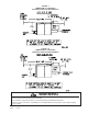
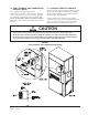
INSTALLATION OF FLEXIBLE CONDUIT
THROUGH RETURN AIR OPENING
NOTE: To allow proper clearance between the
control panel and any vent options, 90°
conduit fittings must be used on the back of
the control panel.
INSTALLING CONDUIT (See Figure 10.)
1. Remove conduit access panel if required to gain
access to area behind control panel.
2. Remove low voltage and high voltage knockouts
located in rear of control panel.
3. Run low voltage conduit through 7/8 bushing located
in conduit entrance plate and secure to low voltage
opening in rear of control panel.
4. Run high voltage conduit through 1-3/4 bushing
located in conduit entrance plate and secure to high
voltage opening in rear of control panel.
5. Replace conduit access panel if required to complete
installation.
6. Seal around conduit in conduit entrance plate.
WARNING
Failure to provide a proper electrical ground
could result in electric shock or fire.
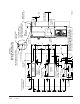
15. WIRING – MAIN POWER
Refer to unit rating plate for wire sizing information
and maximum fuse or “HACR” type circuit breaker
size. Each outdoor unit is marked with a “Minimum
Circuit Ampacity”. This means that the field wiring
used must be sized to carry that amount of current. All
models are suitable only for connection with copper
wire. Each unit and/or wiring diagram will be marked -
“Use Copper Conductors Only”. These instructions
must be adhered to. Refer to the National Electrical
Code (NEC) for complete current carrying capacity
data on the various insulation grades of wiring material.
All wiring must conform to NEC and all local codes.
The electrical data lists fuse and wire sizes (75° C
copper) for all models.
The unit rating plate lists a “Maximum Time Delay
Relay Fuse” or “HACR” type circuit breaker that is to
be used with the equipment. The correct size must be
used for proper circuit protection and also to assure that
there will be no nuisance tripping due to the momentary
high starting current of the compressor motor.
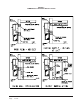
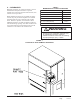
The disconnect access door on this unit may be locked
to prevent unauthorized access to the disconnect. To
convert for the locking capability bend the tab located
in the bottom left hand corner of the disconnect opening
under the disconnect access panel straight out. This tab
will now line up with the slot in the door. When shut, a
padlock may be placed through the hole in the tab
preventing entry.
See “Start Up” section for important information on
three phase scroll compressor start ups.
WARNING
For your personal safety, turn off electric
power at service entrance panel before
making any electrical connections. Failure to
do so could result in electric shock or fire.
WARNING
Failure to provide an electrical power supply
shut off means could result in electric shock
or fire.