INSTALLATION INSTRUCTIONS WALL MOUNTED PACKAGE HEAT PUMPS MODELS W18H1 W24H1 W30H1 W36H1 W42H1 W48H1 W60H1 Bard Manufacturing Company, Inc. Bryan, Ohio 43506 Since 1914...Moving ahead just as planned.
Contents Getting Other Information and Publications Wall Mount General Information Wall Mount Model Nomenclature ............................ Shipping Damage .................................................... General ................................................................ Duct Work ................................................................ Filters ................................................................ Fresh Air Intake .......................................................
GETTING OTHER INFORMATION AND PUBLICATIONS These publications can help you install the air conditioner or heat pump. You can usually find these at your local library or purchase them directly from the publisher. Be sure to consult current edition of each standard. FOR MORE INFORMATION, CONTACT THESE PUBLISHERS: ACCA Air Conditioning Contractors of America 1712 New Hampshire Ave. N.W.
WALL MOUNT GENERAL INFORMATION HEAT PUMP WALL MOUNT MODEL NOMENCLATURE W 42 H 1 – A 10 X X X X KW CAPACITY 18 - 1½ Ton 24 - 2 Ton 30 - 2½ Ton 36 - 3 Ton 42 - 3½ Ton 48 - 4 Ton 60 - 5 Ton VOLTS & PHASE A - 230/208/60/1 B - 230/208/60/3 C - 460/60/3 H - Heat Pump VENTILATION OPTIONS X - Barometric Fresh Air Damper (Standard) B - Blank-off Plate M - Motorized Fresh Air Damper V - Commercial Ventilator - Motorized with Exhaust E - Economizer (Internal) - Fully Modulating with Exhaust R - Energy Re
DUCT WORK FILTERS All duct work, supply and return, must be properly sized for the design airflow requirement of the equipment. Air Conditioning Contractors of America (ACCA) is an excellent guide to proper sizing. All duct work or portions thereof not in the conditioned space should be properly insulated in order to both conserve energy and prevent condensation or moisture damage. A 1-inch throwaway filter is standard with each unit. The filter slides into position making it easy to service.
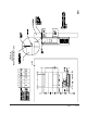
INSTALLATION INSTRUCTIONS WALL MOUNTING INFORMATION 1. Two holes for the supply and return air openings must be cut through the wall as shown in Figure 3. 2. On wood frame walls, the wall construction must be strong and rigid enough to carry the weight of the unit without transmitting any unit vibration. 3. Concrete block walls must be thoroughly inspected to insure that they are capable of carrying the weight of the installed unit.
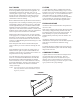
FIGURE 2 Dimensions of Basic Unit for Architectural and I nstallation Requirements (Nominal) MODEL WIDTH DEPTH HEIGHT SUPPLY (W) (D) (H) A B RETURN C B E F G I J K L M N O P Q R S T W18H1 33.300 W24H1 17.125 70.563 7.88 19.88 11.88 19.88 35.00 18.50 25.75 20.56 26.75 28.06 29.25 27.00 2.63 34.13 22.06 10.55 5.00 12.00 5.00 W30H1 38.200 W36H1 17.125 70.563 7.88 27.88 13.88 27.88 40.00 18.50 25.75 17.93 26.75 28.75 29.25 27.00 2.63 39.13 22.75 9.14 5.00 12.00 5.00 W42H1 42.
Manual 2100-511 Page 8 of 27 FIGURE 3A W18H1, W24H1 MOUNTING INSTRUCTIONS
Manual Page 2100-511 9 of 27 FIGURE 3B W30H1, W36H1 MOUNTING INSTRUCTIONS
Manual 2100-511 Page 10 of 27 FIGURE 3C W42H1, W48H1, W60H1 MOUNTING INSTRUCTIONS
FIGURE 4 ELECTRIC HEAT CLEARANCE W30H1, W36H1, W42H1, W48H1, W60H1 SIDE SECTION VIEW OF SUPPLY AIR DUCT FOR WALL MOUNTED UNIT SHOWING 1/4 INCH CLEARANCE TO COMBUSTIBLE SURFACES. WARNING A minimum of 1/4 inch clearance must be maintained between the supply air duct and combustible materials. This is required for the first 3 feet of ducting. It is important to insure that the 1/4 inch minimum spacing is maintained at all points.
FIGURE 5 WALL MOUNTING INSTRUCTIONS SEE FIGURE 3 – MOUNTING INSTRUCTIONS FIGURE 6 WALL MOUNTING INSTRUCTIONS SEE UNIT DIMENSIONS, FIGURE 2, FOR ACTUAL DIMENSIONS IF REQUIRED IF REQUIRED Manual 2100-511 Page 12 of 27
FIGURE 7 COMMON WALL MOUNTING INSTALLATIONS Manual Page 2100-511 13 of 27
WIRING – MAIN POWER WIRING – LOW VOLTAGE WIRING Refer to the unit rating plate for wire sizing information and maximum fuse or “HACR” type circuit breaker size. Each outdoor unit is marked with a “Minimum Circuit Ampacity”. This means that the field wiring used must be sized to carry that amount of current. Depending on the installed KW of electric heat, there may be two field power circuits required. If this is the case, the unit serial plate will so indicate.
START UP THESE UNITS REQUIRE R-410A REFRIGERANT AND POLYOL ESTER OIL. REMEMBER: When adding R-410A refrigerant, it must come out of the charging cylinder/tank as a liquid to avoid any fractionation, and to insure optimal system performance. Refer to instructions for the cylinder that is being utilized for proper method of liquid extraction. GENERAL: 1. Use separate service equipment to avoid cross contamination of oil and refrigerants. 2. Use recovery equipment rated for R-410A refrigerant. 3.
START UP (Continued) IMPORTANT INSTALLER NOTE PHASE MONITOR For improved start up performance wash the indoor coil with a dish washing detergent. All units with three phase scroll compressors are equipped with a 3 phase line monitor to prevent compressor damage due to phase reversal. HIGH & LOW PRESSURE SWITCH All W**H wall mounted air conditioner series models are supplied with a remote reset for the high and low pressure switch.
SEQUENCE OF OPERATION COOLING – Circuit R-Y makes at thermostat pulling in compressor contactor, starting the compressor and outdoor motor. The G (indoor motor) circuit is automatically completed on any call for cooling operation or can be energized by manual fan switch on subbase for constant air circulation. HEATING – A 24V solenoid coil on reversing valve controls heating cycle operation.
FIGURE 8 DEFROST CONTROL BOARD Manual 2100-511 Page 18 of 27
TROUBLESHOOTING SOLID STATE HEAT PUMP CONTROL TROUBLESHOOTING PROCEDURE 1. NOTE: A thorough understanding of the defrost cycle sequence is essential. Review that section earlier in this manual prior to troubleshooting the control. Turn on AC power supply to unit. 2. Turn thermostat blower switch to “fan on” – the indoor blower should start. (If it doesn’t, troubleshoot indoor unit and correct problem.) 3. Turn thermostat blower to “auto” position. Indoor blower should stop.
CHECKING TEMPERATURE SENSOR OUTSIDE UNIT CIRCUIT 1. Disconnect temperature sensor from board and from outdoor coil. 2. Use an ohmmeter and measure the resistance of the sensor. Also use ohmmeter to check for short or open. 3. Check resistance reading to chart of resistance. Use sensor ambient temperature. (Tolerance of part is ± 10%.) 4. If sensor resistance reads very low, then sensor is shorted and will not allow proper operation of the heat pump control. 5.
TROUBLESHOOTING FAN BLADE SETTING DIMENSIONS Shown in Figure 9 is the correct fan blade setting for proper air delivery across the outdoor coil. Refer to Table 2 for unit specific dimension. Any service work requiring removal or adjustment in the fan and/or motor area will require that the dimensions below be checked and blade adjusted in or out on the motor shaft accordingly. REFRIGERANT CHARGE The correct system R-410A charge is shown on the unit rating plate.
TABLE 4A COOLING PRESSURE TABLE Model W18H1 W24H1 W30H1 W36H1 W42H1 W48H1 W60H1 Air Temperature Entering Outdoor Coil °F Return Air Temperature Pressure 75 deg. D B 62 deg. WB Low S i de High Side 132 292 134 311 137 332 138 353 140 376 142 400 144 424 146 450 148 477 150 505 80 deg. D B 67 deg. WB Low S i de High Side 141 299 143 319 146 340 148 362 150 386 152 410 154 435 156 462 158 489 160 518 85 deg. D B 72 deg.
TABLE 5 Electrical Specifications — W**H Series Si ngle C i rcui t Model W18H1- A00, A0Z A 04 3 A 08 W24H1- A00, A0Z A 04 3 A 08 W24H1- B00, B0Z B 06 W24H1- C 00, C 0Z C 06 W30H1- A00, A0Z* A 05* 3 A 10* W30H1- B00, B0Z* B 06 3 B 09* W30H1- C 00, C 0Z* C 06 3 C 09* C 15 W36H1- A00, A0Z* A 05 3 A 10* 5 A 15 W36H1- B00, B0Z* B 06 3 B 09* 5 B 15 W36H1- C 00, C 0Z* C 06 3 C 09* C 15 W42H1- A00, A0Z A 05 3 A 10 5 A 15 W42H1- B00, B0Z B 06 3 B 09 5 B 15 W42H1- C 00, C 0Z C 06 3 C 09 5 C 15 W48H1- A00, A0Z A 04 A
TABLE 6 RECOMMENDED AIRFLOW Model Rated C FM * Rated ESP * Recommended Airflow Range Factory Speed Connection W18H 600 1 .30 575 - 725 High W24H 800 .20 700 - 950 High W30H 1000 .40 930 - 1300 High W36H 1100 .30 930 - 1350 High W42H 1400 .30 1600 - 1150 High W48H 1550 .20 1750 - 1285 High W60H 1650 .30 1950 - 1375 High * Rated CFM and ESP on high speed tap. 1 Rated CFM and ESP on low speed tap. TABLE 7 INDOOR BLOWER PERFORMANCE E.S.P. In H 2O .0 .1 .2 .3 .4 .
TABLES 8 MAXIMUM ESP OF OPERATION ELECTRIC HEAT ONLY Front Outlet Model Model S p eed K W Model ESP W18H1 W24H1 A 00 A 04 A 08 .50 .50 .40 W24H1 B 00 B 06 .50 .50 W24H1 C 00 C 06 .50 .50 Top Outlet Low S p eed High S p eed Low S p eed High S p eed W30H1 W36H1 A 00 A 05 A 10 A 15 .50 .40 .35 .35 .50 .50 .40 .40 .50 .40 .25 NA .50 .50 .40 NA W30H1 W36H1 B 00 B 06 B 09 B 15 .50 .40 .35 .35 .50 .50 .45 .45 .50 NA .30 NA .50 NA .40 NA W30H1 W36H1 C 00 C 06 C 09 C 15 .50 .50 .30 .
EHWH02A-A04 X EHWH02A-A08 X EHW24H-A04 X EHW24H-A08 X EHW24H-B06 EHWH30-A05 X EHWH30-A10 X EHWH36-A05 X EHWH36-A10 X EHWH36-A15 X W60H1-C W60H1-B W60H1-A W48H1-C X EHW36H-B06 X EHWH03-B09 X X EHW30H-B15 X EHWC03A-C06 X X EHWH42-A05 X X EHWH42-A10 X X EHWH42-A15 X X EHWH-04-A20 X X EHWH05-B06 X X EHWH05-B09 X X X EHWH05-B15 X X X EHWH42-C06 X EHWH05A-C09 X X X EHWH05A-C15 X X X EHWH04-A15 X EHWH04-A10 X EHW05H-B18 CIRCUIT BREAKER (WMCB) &
Part Number Description W18, W24 W30, W36 W42, W48, W60 TABLE 11 VENT & CONTROL OPTIONS CMC-14 ODT X X X CMC-15 Start Kit (230V 1-Phase only) 1 X X X SK111 Start Kit (230V 1-Phase only) 2 X X X CMC-28 LA C X X X BFAD-2 Barometric Fresh Air Damper - Standard X BOP-2 Blank Off Plate X MFAD-2 Motorized Fresh Air Damper X CRV-2 Commercial Ventilator - Spring Return X EIFM-2B Economizer X ERVF-A2 Energy Recovery Ventilator - 230 Volt X BFAD-3 Barometric Fresh Air Damp