INSTALLATION INSTRUCTIONS WALL MOUNTED PACKAGE AIR CONDITIONERS MODELS W48A23 W60A23 W48L23 W60L23 Bard Manufacturing Company, Inc. Bryan, Ohio 43506 Since 1914...Moving ahead just as planned.
Contents Getting Other Information and Publications 3 Wall Mount General Information Wall Mount Model Nomenclature............................... 4 Shipping Damage...................................................... 4 General .................................................................. 4 Duct Work.................................................................. 5 Condensate Drain ..................................................... 5 Filters .....................................................
GETTING OTHER INFORMATION AND PUBLICATIONS These publications can help you install the air conditioner or heat pump. You can usually find these at your local library or purchase them directly from the publisher. Be sure to consult current edition of each standard. FOR MORE INFORMATION, CONTACT THESE PUBLISHERS: ACCA Air Conditioning Contractors of America 1712 New Hampshire Ave. N.W.
WALL MOUNT GENERAL INFORMATION AIR CONDITIONER WALL MOUNT MODEL NOMENCLATURE W 48 MODEL NUMBER A 2 3 A 10 REVISIONS CAPACITY 48 - 4 Ton 60 - 5 Ton A - Air Conditioner L - Left Hand Air Conditioner B X X X A CONTROL MODULES (See Spec.
DUCT WORK CONDENSATE DRAIN All duct work, supply and return, must be properly sized for the design airflow requirement of the equipment. Air Conditioning Contractors of America (ACCA) is an excellent guide to proper sizing. All duct work or portions thereof not in the conditioned space should be properly insulated in order to both conserve energy and prevent condensation or moisture damage. A plastic drain hose extends from the drain pan at the top of the unit down to the unit base.
INSTALLATION INSTRUCTIONS WALL MOUNTING INFORMATION 1. Two holes for the supply and return air openings must be cut through the wall as shown in Figure 1 or 2. Figure 1 is for models W48A23 and W60A23. 2. On wood frame walls, the wall construction must be strong and rigid enough to carry the weight of the unit without transmitting any unit vibration. WARNING Fire hazard can result if 1/4 inch clearance to combustible materials for supply air duct is not maintained. 3.
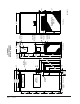
Manual Page 2100-594 7 of 19 31.50 13.50 Front View Condenser Airflow is Blowthrough on All Models 42.00 Low Voltage Electrical Entrances Ventilation Air Electrical Entrances Circuit Breaker Disconnect Access Panel (Lockable) Heater Access Panel Right Side View Electric Heat 22.25 4.56 3.31 Side Wall Mounting Brackets (Built In) .44 Drain 3.25 43.63 40.63 37.13 43.00 34.75 32.50 32.69 23.87 13.88 84.88 18.00 7.
Manual 2100-594 Page 8 of 19 1.88 16.00 16.00 16.00 16.00 16.00 Bottom Installation Bracket Back View Electrical Entrances Return Air Opening Supply Air Opening 43.88 43.00 27.88 10.00 11.00 7.06 3.25 32.81 43.00 84.88 13.88 18.00 7.88 Built In Slope Top 2° Pitch 43.63 40.63 37.13 34.75 32.50 23.88 4.56 3.31 Side Wall Mounting Brackets (Built In) .44 Electric Heat Left Side View Drain 22.
Manual Page 2100-594 9 of 19 7 18" 16" 16" 16" 16" 16" 1 1 1 4" Typ. 1" 3" 28" 4" Typ. Return Opening Supply Opening A 10 8 1/2 B 1 38" C 6 1/2 7 1/4 C Wall Opening and Hole Location View 1 1 62" 62" Dimension is 21" on W70A and W70L Units. 1 72" C 30 REQUIRED DIMENSIONS TO MAINTAIN RECOMMENDED 1" CLEARANCE FROM COMBUSTIBLE MATERIALS D 28 1/2 REQUIRED DIMENSIONS TO MAINTAIN 1/4" MIN.
FIGURE 4 ELECTRIC HEAT CLEARANCE W48A23, W48L23, W60A23, W60L23 SIDE SECTION VIEW OF SUPPLY AIR DUCT FOR WALL MOUNTED UNIT SHOWING 1/4 INCH CLEARANCE TO COMBUSTIBLE SURFACES. WARNING A minimum of 1/4 inch clearance must be maintained between the supply air duct and combustible materials. This is required for the first 3 feet of ducting. It is important to insure that the 1/4 inch minimum spacing is maintained at all points.
FIGURE 5 WALL MOUNTING INSTRUCTIONS SEE FIGURE 3 – MOUNTING INSTRUCTIONS FACTORY SUPPLIED RAIN FLASHING. MOUNT ON UNIT BEFORE INSTALLATION WALL STRUCTURE SUPPLY AIR OPENING SUPPLY AIR OPENING SUPPLY AIR DUCT RETURN AIR OPENING RETURN AIR OPENING RETURN AIR OPENING BOTTOM MOUNTING BRACKET. MOUNT ON WALL BEFORE INSTALLING UNIT.
FIGURE 7 COMMON WALL MOUNTING INSTALLATIONS SUPPLY DUCT MAY BE LOCATED IN AN ATTIC OR BELOW CEILING RAFTERS AS SHOWN RAIN FLASHING RAFTERS RAIN FLASHING FINISHED CEILING SURFACE SUPPLY AIR DUCT SUPPLY AIR DUCT W/ GRILLE FINISHED CEILING SURFACE RETURN AIR OPENING W/ GRILLE RETURN AIR OPENING W/ GRILLE OUTSIDE WALL RAFTERS OUTSIDE WALL FREE AIR FLOW NO DUCT DUCTED SUPPLY RETURN AT UNIT SUPPLY DUCT MAYBE LOCATED IN AN ATTIC OR BELOW CEILING RAFTERS AS SHOWN RAIN FLASHING RAFTERS SUPPLY DUCT MA
WIRING – MAIN POWER WIRING – LOW VOLTAGE WIRING Refer to the unit rating plate for wire sizing information and maximum fuse or “HACR” type circuit breaker size. Each outdoor unit is marked with a “Minimum Circuit Ampacity”. This means that the field wiring used must be sized to carry that amount of current. Depending on the installed KW of electric heat, there may be two field power circuits required. If this is the case, the unit serial plate will so indicate.
START UP THESE UNITS REQUIRE R-410A REFRIGERANT AND POLYOL ESTER OIL. GENERAL: 1. Use separate service equipment to avoid cross contamination of oil and refrigerants. 2. Use recovery equipment rated for R-410A refrigerant. 3. Use manifold gauges rated for R-410A (800 psi/250 psi low). REMEMBER: When adding R-410A refrigerant, it must come out of the charging cylinder/tank as a liquid to avoid any fractionation, and to insure optimal system performance.
START UP (Continued) IMPORTANT INSTALLER NOTE PHASE MONITOR For improved start up performance wash the indoor coil with a dish washing detergent. All units with three phase scroll compressors are equipped with a 3 phase line monitor to prevent compressor damage due to phase reversal. HIGH & LOW PRESSURE SWITCH All W**A/W**L wall mounted air conditioner series models are supplied with a remote reset for the high and low pressure switch.
SEQUENCE OF OPERATION Alarm Relay Output COOLING – Circuit R-Y makes at thermostat pulling in compressor contactor, starting the compressor and outdoor motor. (See NOTE under Condenser Fan Operation if equipped with Low Ambient Control.) The G (indoor motor) circuit is automatically completed by the thermostat on any call for cooling operation or can be energized by manual fan switch on subbase for constant air circulation.
TROUBLESHOOTING REMOVAL OF FAN SHROUD FAN BLADE SETTING DIMENSIONS Shown in Figure 8 is the correct fan blade setting for proper air delivery across the outdoor coil. Refer to Table 2 for unit specific dimension. 1. Disconnect all power to the unit. Any service work requiring removal or adjustment in the fan and/or motor area will require that the dimensions below be checked and blade adjusted in or out on the motor shaft accordingly. 3. Remove screws holding fan shroud to condenser and bottom.
TABLE 5 COOLING PRESSURE TABLE Model W48A2/L2 W60A2/L2 Air Temperature Entering Outdoor Coil °F Return Air Temp (DB/WB) Pressure 75 80 85 90 95 100 105 110 115 120 75/62 Low Side High Side 117 355 119 378 121 403 123 427 125 454 127 482 129 510 131 539 133 570 135 603 80/67 Low Side High Side 125 364 127 388 129 413 132 438 134 466 136 494 138 523 140 553 142 585 144 618 85/72 Low Side High Side 129 377 131 402 134 427 137 453 139 482 141 511 143 541 145 572
Part Number Description W60A23 W48A23 TABLE 7 OPTIONAL ACCESSORIES CMC-15 Start Kit X X WMCB-09A WMCB-08A Circuit Breaker Kit Circuit Breaker Kit X X TABLE 8 ELECTRIC HEAT W60A23 Model 240V-1 208V-1 KW Amps BTUH Amps BTUH 5 20.8 17,050 18.1 12,800 10 41.6 34,130 36.2 25,600 W48A23 & W48L23 ARE NOT APPROVED FOR USE WITH ELECTRIC HEAT.