INSTALLATION INSTRUCTIONS ECONOMIZER WITH EXHAUST MODEL WGEIFM-3C WGEIFM-5C WGSEIFM-5 For Use with Bard 3 - 5 Ton Step Capacity and 2 - 5 Ton Single Stage Wall Mount Air Conditioners with Gas Heat Bard Manufacturing Company, Inc. Bryan, Ohio 43506 Since 1914...Moving ahead just as planned.
CONTENTS General General Information ................................................. Unpacking ................................................................ Description ............................................................... Models ................................................................ Figures 3 3 3 3 Installation Basic Installation .......................................... 4, 5, 7, 8 Economizer Sequence of Operation Condition A – Cool Outdoors .................................
GENERAL GENERAL INFORMATION DESCRIPTION The ventilator should only be installed by a trained heating and air conditioning technician. These instructions serve as a guide to the technician installing the ventilator package. They are not intended as a step by step procedure with which the mechanically inclined owner can install the package.
INSTALLATION BASIC INSTALLATION 1. Unpack the ventilator assembly which includes the integral ventilator with attached electrical harness, blank-off plate and miscellaneous hardware. WARNING Open and lock unit disconnect switch before installing this accessory to prevent injury or death due to electrical shock or contact with moving parts. Turn thermostat to off. 2. Remove and save the existing exterior blower access and service access panels (see Figure 1). 3.
. Install ventilator sheet metal assembly by inserting the ventilator into the unit – centering between the tubing on the left and the control panel on the right. Once the ventilator is fully inserted, slide the ventilator to align screw hole through the front of the condenser grille. (See Figure 2.) IMPORTANT: Position front lip of ventilator on top of front grille and condenser partition. (See Figure 2 inset.) This is important to ensure proper drainage of any water entering damper assembly. 6.
FIGURE 3 INSTALL LOOSE PIECE WIRE HARNESS PLUG ROUTE WIRES THROUGH WIRE MOUNT, AND INTO HOLE AT REAR OF UNIT INTO LOW VOLTAGE TERMINAL BLOCK AREA PLUG TO SECURE INTO FILTER TRAY MIS-2415 Manual 2100-498C Page 6 of 17
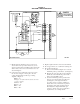
FIGURE 4 WGSEIFM-5 WIRING DIAGRAM 6 ENTHALPY SENSOR 6 4 RED + CONTROL PANEL ORANGE S 7 7 BLACK 1 3 4 6 7 9 A B TR TR1 BROWN + Sr + 7 5 7 1 7 7 3 2 ORANGE YELLOW Y PURPLE 7 PINK 4 T T1 P P1 1 1 2 2 3 3 6 6 5 5 BLACK 7 9 * ELECTRICAL SHOCK HAZARD * DISCONNECT POWER BEFORE SERVICING 7 7 So BK C O G R Y Y1 PR Y PK Y2 UNIT 24 VOLT 7 F 4 BLUE LOGIC MODULE 16 DANGER O CONROL RELAY 5 8 ! ORANGE EIFM 4 TERMINAL STRIP E BL W1 1 RED RED W
EXAMPLE: 1. Measure return air temperature (RAT) (assume 75° F for example). 2. Measure outdoor air temperature (OAT) (assume 60° F for example). 3. Calculate the mixed air temperature (MAT) which will result from the desired combination of OAT (10 percent) and RAT (90 percent). .1 OAT + .9 RAT = MAT or substituting example values .1 (60° F) + .9 (75° F) = 73.75° F 4. Adjust the minimum position potentiometer knob until proper mixed air temperature as calculated above is reached.
FIGURE 5 ECONOMIZER LOGIC MODULE Manual 2100-498C Page 9 of 17
WG3S Ventilation Airflow 700 600 Ventilation Airflow (CFM) 500 Stage #2 Operation 400 Blower Only & Stage #1 Operation 300 200 100 0 0 2.5 5 7.5 10 12.5 15 17.5 20 22.5 25 27.5 30 Vent Position WG4S Ventilation Airflow 900 800 Ventilation Airflow (CFM) 700 600 Stage #2 Operation 500 Stage #1 Operation 400 Blower Only 300 200 100 0 0 2.5 5 7.5 10 12.5 15 Vent Position Manual 2100-498C Page 10 of 17 17.5 20 22.5 25 27.
WG5S Ventilation Airflow 1000 900 800 Ventilation Airflow (CFM) 700 600 500 Stage #2 Operation 400 Stage #1 Operation 300 Blower Only 200 100 0 0 2.5 5 7.5 10 12.5 15 17.5 20 22.5 25 27.
W24G EIFM Airflow VersusPosition - Low Speed 600 550 500 Fresh Air CFM 450 400 350 Free Blow 300 .15" ESP 250 .30" ESP 200 150 100 50 0 closed A B C D Open Damper Position W24G EIFM Airflow VersusPosition - Medium Speed 700 650 600 550 Fresh Air CFM 500 450 400 350 Free Blow 300 .15" ESP 250 .30" ESP 200 150 100 50 0 closed A B C D Open Damper Position W24G EIFM Airflow VersusPosition - High Speed 750 700 650 600 Fresh Air CFM 550 500 450 Free Blow 400 350 .15" ESP 300 .
W30-36G EIFM Airflow VersusPosition - Low Speed 650 600 550 Fresh Air CFM 500 450 400 350 Free Blow 300 .15" ESP 250 .30" ESP 200 150 100 50 0 closed A B C D Open Damper Position W30-36G EIFM Airflow VersusPosition - Medium Speed 750 700 650 600 Fresh Air CFM 550 500 450 400 350 Free Blow 300 .15" ESP 250 .
W42-60G EIFM Airflow VersusPosition - Low Speed 650 600 550 Fresh Air CFM 500 450 400 350 300 Free Blow 250 0.15" ESP 200 0.30" ESP 150 100 50 0 closed A B C D Open Damper Position Fresh Air CFM W42-60G EIFM Airflow VersusPosition - Medium Speed 800 750 700 650 600 550 500 450 400 350 300 250 200 150 100 50 0 Free Blow 0.15" ESP 0.
FIGURE 6 ECONOMIZER OPERATION FOR SINGLE COMPRESSOR UNIT Manual 2100-498C Page 15 of 17
ECONOMIZER SEQUENCE OF OPERATION If second stage closes on the thermostat, the dampers return to the closed or minimum position setting and the compressor starts for mechanical cooling. CONDITION A — COOL OUTDOORS First stage cooling closes and powers the economizer dampers to economizer mode and the indoor blower starts. Mixed Air Sensor senses a mixture of return air and outdoor air and modulates the dampers accordingly. Compressor operation is inhibited. (See Figure 7.
CONDITION B — WARM OUTDOORS First stage cooling cycles the compressor and dampers remain in mechanical cooling mode.