INSTALLATION INSTRUCTIONS WALL MOUNTED PACKAGE HEAT PUMP Models WH184 WH242 Bard Manufacturing Company Bryan, Ohio 43506 Since 1914...Moving ahead just as planned.
Contents Getting Other Informations and Publications Wall Mount General Information Heat Pump Wall Mount Model Nomenclature .......... Shipping Damage .................................................... General ................................................................ Duct Work ................................................................ Filters ................................................................ Fresh Air Intake ........................................................
Getting Other Information and Publications These publications can help you install the air conditioner or heat pump. You can usually find these at your local library or purchase them directly from the publisher. Be sure to consult current edition of each standard. For more information, contact these publishers: ACCA Air Conditioning Contractors of America 1712 New Hampshire Ave. N.W.
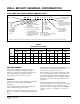
WALL MOUNT GENERAL INFORMATION HEAT PUMP WALL MOUNT MODEL NOMENCLATURE WH 24 2 — A 08 X X X X X B MODEL NUMBER REVISIONS CAPACITY 18 - 1 1/2 Ton 24 - 2 Ton 36 - 3 Ton 48 - 4 Ton 60 - 5 Ton VENTILATION OPTIONS X - Barometric Fresh Air Damper (Standard) B - Blank-off Plate M - Motorized Fresh Air Damper V - Commercial Room Ventilator Motorized with Exhaust E - Economizer (Internal) - Fully Modulating with Exhaust R - Energy Recovery Ventilator with Exhaust KW VOLTS & PHASE A - 230/208/60/1 B - 230/208/
Manual Page 2100-423 3 FIGURE 1 UNIT DIMENSIONS MIS-992
TABLE 2 ELECTRICAL SPECIFICATIONS SINGLE CIRCUIT 1 No.
Ducts through the walls must be insulated and all joints taped or sealed to prevent air or moisture from entering the wall cavity. CAUTION Some installations may not require any return air duct. A metallic return air grille is required with installations not requiring a return air duct. The spacing between louvers on the grille shall not be larger than 5/8 inches. Any grille that meets the 5/8 inch louver criteria may be used.
INSTALLATION INSTRUCTIONS WALL MOUNTING INFORMATION 3. Mount bottom mounting bracket, if used. 1. These units are secured by wall mounting brackets which secure the unit to the outside wall surface at both sides. A bottom mounting bracket is provided for ease of installation, but is not required. 4. Hook top rain flashing under back bend of top. Top rain flashing is shipped secured to the right side of the back. 2.
FIGURE 3 MOUNTING INSTRUCTIONS Manual Page 2100-423 7 MIS-353
FIGURE 4 WALL MOUNTING INSTRUCTIONS SEE FIGURE 3 – MOUNTING INSTRUCTIONS MIS-548 FIGURE 5 WALL MOUNTING INSTRUCTIONS SEE UNIT DIMENSIONS, FIGURE 1, FOR ACTUAL DIMENSIONS MIS-549 Manual Page 2100-423 8
FIGURE 6 COMMON WALL MOUNTING INSTALLATIONS MIS-550 Manual Page 2100-423 9
WIRING – MAIN POWER Refer to the unit rating plate for wire sizing information and maximum fuse or “HACR” type circuit breaker size. Each outdoor unit is marked with a “Minimum Circuit Ampacity”. This means that the field wiring used must be sized to carry that amount of current. Depending on the installed KW of electric heat, there may be two field power circuits required. If this is the case, the unit serial plate will so indicate. All models are suitable only for connection with copper wire.
WIRING – LOW VOLTAGE WIRING 230/208V, 1 phase and 3 phase equipment dual primary voltage transformers. All equipment leaves the factory wired on 240V tap. For 208V operation, reconnect from 240V to 208V tap. The acceptable operating voltage range for the 240 and 208V taps are: TAP 240 208 RANGE 253 - 216 220 - 187 NOTE: The voltage should be measured at the field power connection point in the unit and while the unit is operating at full load (maximum amperage operating condition).
ELECTRIC HEAT HOLD-OFF ( See Figure 9) In other applications, it is desirable to disable the operation of the electric heat until outdoor temperatures have reached a certain design point. This won't allow the electric heat to come on as second stage heating unless the outdoor temperature is below the set point of the outdoor thermostat.
HEAT ANTICIPATION THERMOSTAT INDICATOR LAMPS Group A and Group B thermostats shown in Table 4 have a fixed heat anticipator for stage 1 with no adjustment required. Stage 2 has an adjustable anticipator for the W2 connection and fixed for the W3 connection. Both the W2 and W3 circuits are controlled by the stage 2 bulb. The only heat anticipator that needs to be checked is stage 2 and it should be set to match the load carried by the W2 circuit.
START UP IMPORTANT INSTALLER NOTE For improved start up performance, wash the indoor coil with a dish detergent. CRANKCASE HEATERS WH241 units are provided with compressor crankcase heat. These models have an insertion well-type heater located in the lower section of the compressor housing. This is a self-regulating type heater that draws only enough power to maintain the compressor at a safe temperature.
PRESSURE SERVICE PORTS High and low pressure service ports are installed on all units so that the system operating pressures can be observed. Pressure curves can be found later in the manual covering all models on both cooling and heating cycles. It is imperative to match the correct pressure curve to the unit by model number. DEFROST CYCLE The defrost cycle is controlled by temperature and time on the solid state heat pump control. See Figure 11.
TROUBLESHOOTING SOLID STATE HEAT PUMP CONTROL TROUBLESHOOTING PROCEDURE 3. Turn thermostat blower switch to “auto” position. Indoor blower should stop. 1. Turn on AC power supply to indoor and outdoor units. 4. Set system switch to “heat” or “cool”. Adjust thermostat to call for heat or cool – the indoor blower, compressor and outdoor fan should start. 2. Turn thermostat blower switch to “fan on” – the indoor blower should start. (If it doesn’t, troubleshoot indoor unit and correct problem.
CHECKING TEMPERATURE SENSOR OUTSIDE UNIT CIRCUIT. 3. Check resistance reading to chart of resistance use ambient temperature. (Tolerance of part is ± 10%.) 1. Disconnect temperature sensor from outdoor coil. 4. If sensor resistance reads very low, then sensor is shorted and will not allow proper operation of the heat pump control. 2. Use an ohmmeter and measure the resistance of the sensor. Also use ohmmeter to check for short or open. 5.
FAN BLADE SETTING DIMENSIONS Shown in Figure 12 are the correct fan blade setting dimensions for proper air delivery across the outdoor coil. Any service work requiring removal or adjustment in the fan and/or motor area will require that the dimensions below be check and blade adjusted in or out on the motor shaft accordingly. The suction line temperatures in Table 7 are based upon 80° F dry bulb/67° F wet bulb (50% R.H.) temperature and rated airflow across the evaporator during cooling cycle.
TABLE 11 – PRESSURE TABLE COOLING Model WH184 WH242 Air Temperature Entering Outdoor Coil °F Return Air Temperature Pressure 75 80 85 90 95 100 105 110 115 75 deg. D B 62 deg. WB Low S i de High Side 74 188 76 202 77 215 79 231 79 247 80 263 82 280 82 297 83 316 80 deg. D B 67 deg. WB Low S i de High Side 79 193 81 207 82 221 84 237 85 253 86 270 88 287 88 305 89 324 85 deg. D B 72 deg.
WH242-A WH242-C WH183-A WH242-B TABLE 13 OPTIONAL ACCESSORIES EHWH02A-A04 EHWA02A-A08 EHWH14-B06 EHWH24B-C06 Heater Packages Heater Packages Heater Packages Heater Packages X X X X BOP-2 BFAD-2 MFAD-2 CRV-2 EIFM-2 WERV-A24 Blank Off Plate Barometric Fresh Air Damper Motorized Fresh Air Damper Classroom Ventilator with Exhaust Economizer with Exhaust Energy Recovery Ventilator X X X X X X X X X X X X X X X X X X X X X X X CMH-3 CMH-7 CMH-9 CMH-14 CHM-15 Low Pressure Control (LPC) Low Ambient