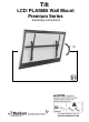
Tilt LCD/ PLASMA Wall Mount Premium Series Assembly instructions 0 56 142 110 50 110051.2 18.01.
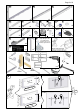
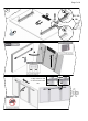
Page 2 of 8 B C 1:5 A x2 E D F H G x2 x2 I M6 x4 x2 K N L 14 x2 x2 P O 10 x6 Q J M6 x2 x8 R M10X1 M6 1:2 20 x4 x2 x4 T S M x2 W 9/16" x2 17 x2 x2 x2 The provided M bolts may change in size according to the evolution of screen market requirements sticker x1 x1 Tools Required 17mm No.2+3 10mm 1 of Back n scree A max 71 cm (27.9") Max 600mm/23.5" 1 rail 1 .5" m/15 400m x a M 2 of Back n scree max 71 cm (27.9") Max 600mm/23.
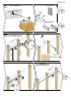
Page 3 of 8 2 H=115mm/4.5" 3A H Center of screen 3B 3A Find stud, Level & Mark left rail 6m 40 m Drill ") (16 L m 10m4") .
Page 4 of 8 4A Drill E 5 A T 3B Drill Level & Mark right rail A H The anchor must be sunk up to 10 mm(3/8") into the plaster coating 10mm (3/8") L A T min 4 X max 9 E 4B
Page 5 of 8 4B Drill Level & Mark right rail A L A E T Xmin 4 max 9 5 Test! 6 50kg/110lbs R
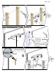
Page 6 of 8 6 X2 X2 K No Force P B H J B O C I C G K N F Back scree of n 10(3.94 90 cm "-35. 4") 10-63 cm (3.94"-24.8") N Up to 49 cm (19.3") Back scree of n 10(3.94 90 cm "-35.4 ") No Force 7 X2 I 8 D 7 Q 10-63 cm (3.94"-24.8") X2 49 - 71 cm (27.
Page 7 of 8 8 x Ma m 9c ") 54 (3.
Page 8 of 8 9 Right Left To release move screen to the right S