3UR7DON &HOOXODU $58 INSTRUCTION MANUAL 1272M001 Manual Revision: 7 - July 2002
Contents 1. Operations Overview Cv2 capabilities . . . . . . . . . . . . . . . . . . . . . . . . . . . What constitutes an alarm? . . . . . . . . . . . . . . . . . How are alarms processed? . . . . . . . . . . . . . . . . . What actions should occur when an alarm is detected? . . . . . . . . . . . . . . . . . . . How do you want to respond to an alarm call? . . . . . . . . . . . . . . . . . . . . . . . . . . What if an alarm is not acknowledged? . . . . . . .
Operations Overview 1-1 1. Operations Overview The purpose of this chapter is to provide an overview of the Cv2 capabilities. Chapter topics are organized in the same order that you would follow in setting up the system. Read this chapter carefully before proceeding with the installation and programming of the Cv2. For more details on configuring the operation through the programming software, refer to Chapter 3, Configuration. 1.
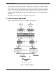
Operations Overview 1-2 Analog inputs convert the voltage level to a digital value and perform a comparison against the programmed low and high setpoints. An alarm is present when the measured value is above or below the setpoint. Alarm messages are spoken using the stored phrase with either “High” or Low” appended depending on which setpoint has been exceeded. The actual reading, including decimal place notation and engineering units, is spoken when the Cv2 is interrogated.
Operations Overview 1-3 The hardware input and output ports are activated in the Points section to become part of the monitoring and control process. There are 30 points which can be referenced to any of the I/O ports. This allows an analog input to be used by more than one point and monitored for multiple setpoints, as would be the case where minor and major alarms are required.
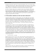
Operations Overview 1-4 For example, to call four telephone numbers, the directory would appear as: 1. [DIAL]2458829 [VOICE] 2. [DIAL]2336700 [VOICE] 3. [DIAL]9842121 [VOICE] 4. [DIAL]9843316 [VOICE] If you want an alert tone to precede the voice message the directory line would look like this: 1. [DIAL]2458829 [ALERT] [VOICE] The next example shows a sequence that is used to call a numeric paging terminal.
Operations Overview 1-5 1.6 What if an alarm is not acknowledged? When the last line in the directory has been completed without receipt of an Acknowledge Code, a two-stage timer is used to determine when the directory sequence is repeated again. This timer has two sections: a Short Timer which operates for the number set in Short Cycles, and a Long Timer which begins after the Short Timer has completed its cycles. This provides a means of varying the repetition cycle over a period of time. 1.
Operations Overview 1-6 1.9 Indicators The Cv2 has four LED indicators to show the operation of the unit and assist in troubleshooting. When the Cv2 is initially powered up, the four LEDs will do the following: & All will turn on for approximately one second. & Hook will flash on and off for one second then go out. & Tone will flash on and off for one second then go out. & Voice will flash on and off for one second then go out. & Alarm will flash on and off for one second then go out.
Operations Overview 1-7 Are the inputs connected properly? For digital inputs that are programmed for standard digital operation, create an alarm condition on the input and confirm that the Alarm LED comes on. Make sure the input is applied long enough for the debounce to time out. If the Alarm indicator does not come on, the problem is not necessarily with the input connection. Check that the input is enabled as a valid point, the associated group is enabled, and the directory is programmed to call out..
Installation 2 2-1 Installation The Cv2 can be installed before or after the configuration has been transferred from the PC to the unit. If the Cv2 is configured in the shop before it is installed in the field, all of the programmed parameters and voices will remain unchanged in the unit’s non-volatile flash memory. 2.1 Antenna requirements The antenna used for your installation will depend on the proximity of the alarm unit to the cellular carrier facility.
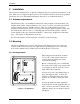
Installation 2-2 2.2.2 Stand-alone model The stand-alone Cv2 can be mounted on a flat surface. Make sure that there is enough room around the unit to make connections. The environment should be clean and dry, with an ambient temperature that does not go below -20oC or above +50oC. Connect a DC power source to the terminals on TB2. The Cv2 requires up to 1.5 Amps to operate; the supply should be sized accordingly. Input power to the unit is protected by a Polyswitch current limiter.
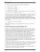
Installation 2-3 2.3.2 +12 volt alarm signal The input will accept an alarm signal that switches between 0 and +12 volts with the wiring arrangement shown in Figure 5. If the signal switches between +12 volts and an open circuit, as in the case of a relay contact, the ‘B’ terminal must be connected to ground to ensure that the logic level goes to ground when the voltage is removed. Figure 5 +12 Volt Input Wiring 2.3.
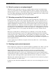
Installation 2-4 2.4 Output port connections The output ports are open collector drivers that can sink up to 500 mA through a load connected to a voltage of up to +50 VDC. If an inductive load Figure 9 Output Wiring such as a relay is connected to an output, install a protective reverse-biased diode across the load to prevent damage to the output from the inductive flyback voltage. Figure 9 shows the connection for an output used as a relay driver. 2.
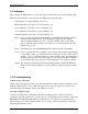
Installation 2-5 Figure 11 Stand-alone Cv2 Figure 12 Packaged Cv2 B1272M001 BARNETT ENGINEERING LTD.
Configuration using the PC 3 3-1 Configuration using the PC This chapter describes how to install the programming software and configure the operation of the Cv2. When the configuration is complete, it can be viewed through the Summary command found on the File pull-down menu. In the summary, Warnings should be checked to ensure that there are no improper settings in the configuration before it is transferred to the Cv2. 3.
Configuration using the PC 3-2 3.4.1 File Operations File Open If you do not want to edit the default database, use the File Open button to select a different configuration file. This will bring up the standard Windows File Open dialog box where you can open another .dat file. File Save As To save the current configuration under a different name, use the Save As button to bring up the standard Windows Save As dialog box. Enter a new name and save the file.
Configuration using the PC 3-3 3.4.6 Directories When an alarm is detected, the Cv2 will perform a specific sequence of events determined by the entries in the directory. Six directories are available, providing different actions for different groups. 3.4.7 Programming The programming section is used to transfer the configuration database between the PC and the Cv2. Recorded voices can also be transferred from the Cv2 and then back. 3.
Configuration using the PC 3-4 debounce times, use the seconds timer to avoid the inaccuracy introduced by the one minute resolution. Default Debounce time: 0.05 sec A Digital input port can also be used to perform special functions in the Cv2. In the Groups section, it can be selected for the Local Acknowledge function, and in the Hardware section it can be set to operate as a Reset Input for a Totalizer.
Configuration using the PC 3-5 Analog Input Setting the input port type to Analog allows measurement of voltages between 0 and +5 volts. As with the other input types, the definition of an analog input is completed in the Points section where the range, setpoints and units are assigned. An Analog port can be changed to one of the other input types by selecting from the Change Input Port drop-down list.
Configuration using the PC 3-6 Each point can be placed into one of the six groups. If a port is used for one of the special functions, the Group section sets the ports. To access a point for configuration, select the Points button to bring up the summary of the settings. Status of the 30 points will be shown along with a brief description of their settings. Highlight the point to be edited, then select it by pressing Enter, double-clicking on the line, or choosing the Edit Line function from the menubar.
Configuration using the PC 3-7 Enabled When a point is enabled, alarm activities will be reported and it can be interrogated for its current status. A disabled point does not produce alarms and cannot be interrogated. Changing the enable flag does not alter any of the other settings for this point. Default Point state: disabled. Digital and Watchdog Points Settings for Watchdog points are the same as for Digital points.
Configuration using the PC 3-8 When the message is spoken, the digits to the left of the decimal (represented by X) and the digits to the right of the decimal (represented by Y) are spoken with the word ‘point’ between them. The format with the decimal at the far right with no ‘Y’ component is spoken without the word ‘point’. Default Decimal Place: no decimal place spoken. Clear Code The Clear Code is used to clear the totalizer to a zero reading.
Configuration using the PC 3-9 Calibrate Calibration of an analog allows the conversion of the input voltage reading to a value that is expressed in engineering units. Setpoints are then assigned to the actual corresponding measurement, and when the point is interrogated, the reading is announced in engineering units. Calibrate is a secondary dialog box that is activated from the Analog Point dialog box.
Configuration using the PC 3-10 0 as the minimum, 10 as the maximum, with Units set to read ‘thousand’ as the prefix before gallons. Once the range of the decimal scale has been entered, then the high and low setpoints can follow. Both setpoints can be used within a single point. If the low setpoint is not required, set it to the decimal minimum; if the high setpoint is not needed, set it to the decimal maximum. Default Decimal Values: Minimum: 0 Maximum: +100.0 Low Setpoint: +25.0 High Setpoint: +75.
Configuration using the PC 3-11 DTMF Off Code When the Cv2 receives the DTMF Off code, it sets the output port to the Off state. After the Off code has been received and the output port cleared, the Cv2 announces the current status of the output. This code can be 1 to 7 digits in length and may use any of the 16 DTMF digits including A, B, C, and D. Default DTMF Off Code: an empty string - no Off Code.
Configuration using the PC 3-12 conditions. If a different type of activity is required, such as after hours or weekends, the change can be quickly made by using another shift to control the Cv2 operation. There are also a number of special function settings that enable outputs and inputs to operate as controls and indicators for some internal Cv2 activities.
Configuration using the PC 3-13 Enable Ack Request At the completion of an alarm announcement sequence, the Cv2 will query the called party with the phrase “Enter Acknowledge Code’. If this prompt is not required, clear the enable setting. Default Ack Request: enabled Timers The Cv2 uses a two-stage timer to schedule the interval between alarm reporting sequences.
Configuration using the PC 3-14 Special Function Outputs Outputs can be assigned to indicate certain conditions within the Cv2. The three special function outputs are: Alarm Active This control allows any one of the eight output ports to be used as an indicator that an alarm is present in this group. The selected output will remain active while an alarm is present, acknowledged or not.
Configuration using the PC 3-15 Only Digital inputs can be used for this purpose. The selection shown in the list box is restricted to inputs that are set to digital in the Hardware section. To use this feature, the input must be selected in the Points section and enabled. Default Special Function Input: NONE. 3.5.4 Directories The Directories contain the sequences of actions that will occur when an alarm is activated in a group.
Configuration using the PC 3-16 Auto Ack If enabled for the group using this directory, the Auto Ack command causes the Cv2 to automatically acknowledge its alarms without receipt of any other code or signal. This command is used when it is anticipated that the called party will have no means of acknowledging the call. Unless absolutely necessary, this command should not be used since there is no assurance that the alarm message was properly received.
Configuration using the PC 3-17 Signal If a DTMF tag is programmed for a point and the Signal command is set, then only the DTMF tag for this point will be sent and the voice message will not be spoken. Signal must be preceded by a Dial command; it cannot be the first entry in the list. It can be used once in a list. Delete Delete removes the selected command from the list. Commands that followed the deleted one are moved to fill in the empty space.
Configuration using the PC 3-18 programming is always available if there is no Access code in the unit. This code can be 1 to 7 digits in length and may use any of the 16 DTMF digits including A, B, C, and D. Default Access Code: an empty string. Shift Change Code The shift that is being used at any particular time is determined by the last time that a Shift Change Code message was received. The Cv2 retains the current shift when it is powered down and returns to that shift when power is restored.
Configuration using the PC 3-19 operational. Data is transferred in four-kilobyte packets at 9600 baud. The configuration database will take two packets to transfer; the number of packets in a voice data transfer will vary depending on how many points are used and how long the messages are. Configuration Data To transfer configuration data, use the two buttons in the Configuration box.
Voice Storage and Configuration with the Telset 4-1 4 Voice Storage and Configuration with the Telset 4.1 Setup After the configuration database has been transferred to the Cv2, it is ready to accept the voice messages that will be used in the alarm reporting process and it is possible to change some of the configuration data that was transferred from the PC. First ensure a database has been downloaded from the PC to the Cv2.
Voice Storage and Configuration with the Telset 4-2 directory menu. The choices at this point are: 0UU - Speak the Directory Codes These codes correspond to buttons found in the Directory Editor dialog box used for PC programming. They are used to enter the new configuration.
Voice Storage and Configuration with the Telset 4-3 If a sequence is entered without a Voice command, the Cv2 will add the word “Warning” when it speaks the line. 3UU Delete current entry Cv2: “beep” This command will remove the selected line from the directory. If there are any lines following the deleted line, they will be moved up to fill in the empty line created by this command. The Cv2 will respond with the new setting for this line.
Voice Storage and Configuration with the Telset 4-4 Pauses between words may cause the recording to terminate. If the message is acceptable, press UU to advance to the next voice. If it is not, keep using 2UU and repeat the message until it is satisfactory, then press UU to accept the current recording. The next prompt you will hear is: Cv2: “Group One is Electrical” Again, use 2UU to record the name of the group, and UU to advance.
Voice Storage and Configuration with the Telset 4-5 8UU - Received Signal Strength Cv2: “Code Eight is One, One, Two, One, ...” The Cv2 speaks a number from One to Thirteen. Each increment corresponds to approximately 5 dBm, with 0 representing roughly -121 dBm and 13 representing -56 dBm. The LEDs show a binary representation of the spoken value, where the ALARM LED is the most significant bit and the HOOK LED is the least significant.
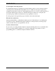
Voice Storage and Configuration with the Telset 4-6 Cv2: "Enter Program Code" Edit Directories Cv2: "Enter Directory Code" Speak Directory Codes Cv2: Speaks the list of Directory Codes described previously , Select Directory ...
Voice Storage and Configuration with the Telset 4-7 Exit Accept Cv2: "Group One is Electrical" Record Cv2: "beep" You: "Mechanical" Cv2: "Group One is Mechanical" Exit Accept And so on for the remaining groups Record Points Cv2: "Point One is Power Failure" Record Cv2: "beep" You: "Generator Low Voltage" Cv2: "Point One is Generator Low Voltage" Exit Accept And so on for the remaining points Enable Groups "Electrical On" or "Electrical Off" Disable this group Cv2: "Electr
Voice Storage and Configuration with the Telset 4-8 Query NAM Cv2: "Code Four is One" or "Code Four is Two" Query MIN Cv2: "Code Five is Two Three Eight ..." Query ESN Cv2: "Code Six is Nine Four Four..." Query RSSI Cv2: "Code Eight is One, One, Two, One ..." User Call Cv2: "beep" B1272M001 - call placed BARNETT ENGINEERING LTD.
Specifications 6-1 5 Specifications 5.1 General Alarm Inputs • 8 inputs: analog or digital, latching or momentary; plug in screw terminal block. • analog: 0 to 5 VDC, 100k input impedance • digital: normally open or normally closed, ground closure or +10 to +30 VDC input; optionally configured for acknowledge input.
Specifications 6-1 Alarm Groups • Alarms can be assigned to one of 8 groups. All alarms in a group use the same directory when calling out. Shifts • Up to 4 shifts can be used. The current setting of the shift instructs a group to use one of the six directories. Interval Timer • Two-stage timer which uses the short interval several times before switching to a long interval. Short and long intervals are adjustable from 1 to 249 minutes; the short timer can be used from 1 to 9 times.
Specifications 6-1 6 Warranty Barnett Engineering Ltd. warrants that all equipment supplied shall be free from defects in material or workmanship at the time of delivery. Such warranty shall extend from the time of delivery for a period of one year. Buyer must provide written notice to Barnett Engineering Ltd. within this prescribed warranty period of any defect.