INSTRUCTION MANUAL
INSTRUCTION MANUAL 1272M001 Manual Revision: 9.
Contents 1 Getting Started 2 Operations Overview . . . . . . . . . . . . . . . . . . . . . . . . . . . . . . . . . . . . 1-1 Cv2 capabilities (Advanced Mode) . . . . . . . . . . . . . . . . . . . . . . . . . . . What constitutes an alarm? . . . . . . . . . . . . . . . . . . . . . . . . . . . . . . How are alarms processed? . . . . . . . . . . . . . . . . . . . . . . . . . . . . . . What actions should occur when an alarm is detected? . . . . . . How do you want to respond to an alarm call? . . . . . .
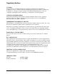
Regulatory Notices CAUTION The ProTalk Cv2, model B1272D, has been certified by the Federal Communications Commission (“FCC”) using the included articulating dual-band dipole antenna. Unauthorized modifications or changes not expressly approved by Barnett Engineering Ltd. could void compliance with regulatory rules, and thereby your authority to use this equipment.
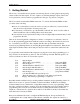
Getting Started 1-1 1. Getting Started The Cv2 is a very flexible device capable of monitoring discrete or analog inputs and reporting alarm conditions at these inputs. It is also capable of controlling multiple outputs. Before the Cv2 is placed into service it must be programmed for the type of operation you require. The Cv2 contains an embedded CDMA transceiver.
Getting Started 1-2 single function called Controls. The number of directories is reduced from 6 to 2 in Basic mode. It is possible to retain the Advanced directory commands even if the overall programming is set for Basic operation. It is important to establish whether Basic or Advanced programming is suitable for your application. The mode is set by the configuration uploaded from the PC and cannot be altered using the programming phone.
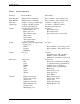
Getting Started Table 1 1-3 Mode Comparison Function Input debounce Input NO/NC Input type Output type Groups Points Alarms Directories General B1272M001 Advanced Mode Independent for each input Independent for each input 8 inputs - 1 analog, 4 digital types 8 outputs - On/Off or timed 4 can be special function 6 groups each with separate Acknowledge code Interrogate code Short and long timer Shift control Group enable Ack request enable Auto Ack enable 30 points, can be any input/output Using gro
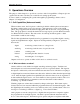
Operations Overview 2-1 2. Operations Overview The purpose of this chapter is to provide an overview of the Cv2 capabilities. Chapter topics are organized in the same order that you would follow in setting up the system. For more details on configuring the operation through the programming software, refer to Chapter 3, Configuration. 2.
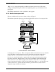
Operations Overview 2-2 “High” or Low” appended depending on which setpoint has been exceeded. The actual reading, including decimal place notation and engineering units, is spoken when the Cv2 is interrogated. The latching alarm function is also available for analog inputs. 2.1.3 How are alarms processed? The way in which the Cv2 processes alarms is shown in Figure 1.
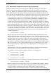
Operations Overview 2-3 2.1.4 What actions should occur when an alarm is detected? All alarm conditions will be processed by placing a call on the cellular phone. The called number and the activities that occur with different alarms are determined by entries in the directories. A directory contains the sequence of actions that will occur when a group has an active alarm.
Operations Overview 2-4 alarm before the Cv2 advances to the next line in the directory. This can be done by using the Wait command on its own line; the entry below will cause a four minute delay before the next line is executed. 1. [DIAL]2458829 [WAIT]4 [DTMF]4567 2. [WAIT]240 Directory lines can be added, removed, or modified and new lines can be inserted between existing lines. 2.1.
Operations Overview 2-5 allowing access to alarm information or other control functions. At the highest level, the call is answered but there are no voice prompts; the caller has ten seconds to enter the Access Code. Each group of alarms has its own Interrogate Code. When the code is entered, the alarm status for points in that group is spoken. For digital and watchdog points, the stored phrase for that point is spoken.
Operations Overview 2-6 2.2.1 What constitutes an alarm? The signal at the input is conditioned by a debounce timer that ensures the level is valid before accepting it. An alarm has normal and alarm states that can be defined as either when the input is high or low. After the input signal has been qualified by the debounce timer, it can be registered as an alarm when the input is active, or it can be latched to detect a pulsed condition. 2.2.
Operations Overview 2-7 2.2.4 How do you want to respond to an alarm call? After the Cv2 has finished speaking the alarm messages, it prompts the called party with the phrase “Enter Acknowledge Code” and then waits five seconds for the code to be returned. If the code is received, it will terminate any further call out activities until a new alarm occurs; otherwise, it will proceed to the next line in the directory.
Operations Overview 2-8 2.3 Indicators The Cv2 has four LED indicators to show the operation of the unit and to assist in troubleshooting. When the Cv2 is initially powered up, the four LEDs will do the following: C All will turn on for approximately one second. C Hook will flash on and off for one second then go out. C Tone will flash on and off for one second then go out. C Voice will flash on and off for one second then go out. C Alarm will flash on and off for one second then go out.
Operations Overview 2-9 Are the inputs connected properly? For digital inputs that are programmed for standard digital operation, create an alarm condition on the input and confirm that the Alarm LED comes on. Make sure the input is applied long enough for the debounce to time out. If the Alarm indicator does not come on, the problem is not necessarily with the input connection. Check that the input is enabled as a valid point, the associated group is enabled, and the directory is programmed to call out..
Installation 3 3-1 Installation The Cv2 can be installed before or after the configuration has been transferred from the PC to the unit. If the Cv2 is configured in the shop before it is installed in the field, all of the programmed parameters and voices will remain unchanged in the unit’s non-volatile memory. 3.1 Antenna requirements The ProTalk Cv2 is supplied with an 8" dual band articulating antenna. This antenna should be mounted vertically for best operation.
Installation 3-2 3.2.2 Stand-alone model The stand-alone Cv2 can be mounted on a flat surface. Make sure that there is enough room around the unit to make connections. The environment should be clean and dry, with an ambient temperature that does not go below -30oC or above +50oC. Connect a DC power source to the terminals on TB2. The Cv2 requires up to 1.2 Amps to operate; the supply should be sized accordingly. Input power to the unit is protected by a Polyswitch current limiter.
Installation 3-3 3.3.2 +12 volt alarm signal The input will accept an alarm signal that switches between 0 and +12 volts with the wiring arrangement shown in Figure 6. If the signal switches between +12 volts and an open circuit, as in the case of a relay contact, the ‘B’ terminal must be connected to ground to ensure that the logic level goes to ground when the voltage is removed. Figure 6 +12 Volt Input Wiring 3.3.
Installation 3-4 3.4 Output port connections The output ports are open collector drivers that can sink up to 500 mA through a load connected to a voltage of up to +50 VDC. If an inductive load such as a relay is connected to an output, install a protective reverse-biased diode across the load to prevent damage to the output from the inductive flyback voltage. Figure 10 shows the connection for an output used as a relay driver. Figure 10 Output Wiring 3.
Installation 3-5 Figure 12 Stand-alone Cv2 Figure 13 Packaged Cv2 B1272M001 BARNETT ENGINEERING LTD.
Configuration using the PC 4 4-1 Configuration using the PC This chapter describes how to install the programming software and configure the operation of the Cv2. When the configuration is complete, it can be viewed through the Summary command found on the File pull-down menu. In the summary, Warnings should be checked to ensure that there are no improper settings in the configuration before it is transferred to the Cv2. 4.
Configuration using the PC 4-2 4.5 Program Functions - Advanced mode The menu and taskbar for the advanced mode is shown below: File Operations File Open If you do not want to edit the default database, use the File Open button to select a different configuration file. This will bring up the standard Windows File Open dialog box where you can open another .dat file.
Configuration using the PC 4-3 Groups Each of the six groups can be set to provide different alarm reporting operations for selected points. Points In the points section, any of the hardware inputs and outputs can be selected for the Cv2 to use as alarm reporting or remote control functions. There are 30 points available. Directories When an alarm is detected, the Cv2 will perform a specific sequence of events determined by the entries in the directory.
Configuration using the PC 4-4 way to get the unit operational when in the Advanced mode. If the Cv2 uses any of the special port functions -- Alarm Active, New Alarm, Acknowledge Received, Local Acknowledge or the Totalizer Reset Input -- you must consider the relationship between these functions and the Hardware, Groups and Points sections when configuring the unit. 4.7.1 Hardware section Start with the Hardware section to establish settings for the input and output ports.
Configuration using the PC 4-5 Watchdog Interval timer. Refer to the preceding Digital input description for details on the Debounce timer. Two Watchdog time ranges, seconds and minutes, are available. The seconds range has a maximum value of 1638 seconds (27 minutes) with a resolution of 25 msec. For longer Watchdog times the minutes range should be used. When set to minutes, the Watchdog timer has a maximum value of 65,535 minutes with a resolution of one minute.
Configuration using the PC 4-6 Two timer ranges, seconds and minutes, are available. The seconds range has a maximum value of 1638 seconds (27 minutes) with a resolution of 25 msec. For longer times the minutes range should be used. When set to minutes, the timer has a maximum value of 65,535 minutes with a resolution of one minute. For short times use the seconds timer to avoid the inaccuracy introduced by the one minute resolution.
Configuration using the PC 4-7 Output used to indicate that the phone is ringing. Output used to indicate that the modem is in the connected state. Default Port Selection: Unused, not included in any reporting activities. Point Name The Point Name is a 16-character text field where you can enter a description of the point. This name is used for quick identification in the point summary; otherwise it is not required for operation of the Cv2.
Configuration using the PC 4-8 Decimal Place A decimal place can be inserted into the spoken message for a totalizer. Five decimal locations are available: XXXXX. XXXX.Y XXX.YY XX.YYY X.YYYY When the message is spoken, the digits to the left of the decimal (represented by X) and the digits to the right of the decimal (represented by Y) are spoken with the word ‘point’ between them. The format with the decimal at the far right with no ‘Y’ component is spoken without the word ‘point’.
Configuration using the PC 4-9 announced in engineering units. Calibrate is a secondary dialog box that is activated from the Analog Point dialog box. The relationship between the binary reading from the input analog converter and the decimal value that is used for setpoints and annunciation is established by setting the Binary and Decimal limits.
Configuration using the PC 4-10 Minimum: 0 Maximum: +100.0 Low Setpoint: +25.0 High Setpoint: +75.0 Hysteresis Hysteresis is a quick method of establishing the reset values for the high and low setpoints. After an analog reading has exceeded the setpoint, either high or low, it must pass through the reset value before it is considered to have returned to normal. This prevents a reading that is hovering around a setpoint from constantly going in and out of alarm.
Configuration using the PC 4-11 interval, the output port may have returned to the Off state before the announcement is made. This code can be 1 to 7 digits in length and may use any of the 16 DTMF digits including A, B, C, and D. Default DTMF On Code: an empty string - no On Code. DTMF Off Code When the Cv2 receives the DTMF Off code it sets the output port to the Off state and terminates the timer operation if it is currently running.
Configuration using the PC 4-12 Interrogate Code The Interrogate Code is a 1 to 7 digit DTMF string that is used to make the Cv2 announce the condition of points in the group. Each group can have a unique Interrogate Code, or different groups can use the same code in order to generate the status of all groups at once. Default Interrogate Code: an empty text string. Enable This Group To allow this group to be used for alarm reporting, this setting must be enabled.
Configuration using the PC 4-13 This code can be 1 to 7 digits in length and may use any of the 16 DTMF digits including A, B, C, and D. Default Shift Selection: Directory A for all shifts. Special Function Outputs Outputs can be assigned to indicate certain conditions within the Cv2. The three special function outputs are: Alarm Active This control allows any one of the eight output ports to be used as an indicator that an alarm is present in this group.
Configuration using the PC 4-14 in a line-by-line format. A line represents one complete action, usually a cellular call. Edit the highlighted line by pressing Enter, double-clicking on the line, or selecting the Edit Line command from the menubar in the summary window. Lines can also be removed or inserted. The editor dialog box displays two columns on the left, one for the Command entry and the other for the Value entry, if any. Buttons for each type of command are arranged on the right.
Configuration using the PC 4-15 separated by 100 msec of quiet. Alert must be preceded by a Dial command; it cannot be the first entry in the list. It can be used more than once in a list. Voice The Voice command causes stored voice messages for the Site ID, Group IDs and any points in the alarm state to be spoken. If Voice is the only command after Dial, the Cv2 will speak the alarm message three times or for one minute, whichever comes first.
Configuration using the PC 4-16 Level 2 When the incoming call is answered by the Cv2, only the Site ID is announced; for further access to the Cv2 the caller must enter the Access Code. Level 3 An incoming call results in the Cv2 coming off-hook with no announcement; the Access Code must be entered within ten seconds or the Cv2 will hang up. Default Security Level: Level 1 Access Code An Access Code is needed when calling into a unit configured for security levels 2 or 3.
Configuration using the PC 4-17 Ring Output Ring output is used to select one of the eight outputs to externally indicate that there is an incoming call. The output will follow the ringing cadence if selected. Default Ring Output: None Modem CD Modem Carrier Detect is used to select one of the eight outputs to externally indicate that the modem has connected to an incoming call.
Configuration using the PC 4-18 Configuration Data To transfer configuration data, use the two buttons in the Configuration box. Press the Write To Cv2 button to transmit the configuration database from the PC into the Cv2 or press the Read From Cv2 button to transfer the configuration from the Cv2 to the PC . Voice Messages To transfer voice data, use the buttons in the Voice box. Press the Write to Cv2 button to move voice messages from a file in the PC to the Cv2.
Configuration using the PC 4-19 4.8.2 Control section Use the Control section to configure the hardware outputs if the Cv2 is going to be used for remote control. Three of the control outputs are user programmable and can be individually set for either on/off or timed operation; five outputs are used for the special functions. Format Each control can be either an On/Off or a Timed type.
Configuration using the PC 4-20 keeping the rest of the configuration in basic mode. Insert - Insert a new phone number at the highlighted location Delete - Delete the phone number at the highlighted location Edit - Modify the phone number at the highlighted location Advanced - View or edit the directory with the Advanced editor Acknowledge Code The Acknowledge Code is a 1 to 7 digit DTMF string that is used to acknowledge the directory and stop alarm transmission until a new alarm is detected.
Remote Data Access 5 5-1 Remote Data Access External equipment connected to the serial port can be accessed by calling the Cv2 with a remote modem. The Cv2 can determine whether the data is intended for a remote programming session or if it is to be routed to the attached equipment.
Voice Storage and Configuration with the Telset 6 6-1 Voice Storage and Configuration with the Telset 6.1 Setup The Cv2 can be configured by transferring a database from the PC, either in Basic or Advanced mode, or by using the programming phone.
Voice Storage and Configuration with the Telset 6-2 Directory programming, where the called numbers are entered, requires care to ensure that these numbers are valid. If the Cv2 is unable to successfully complete calls it will take action to ensure that the cellular network is not adversely affected. These actions are detailed in the “Getting Started” section at the beginning of the manual. The following example shows how to enter voice messages using a telephone set.
Voice Storage and Configuration with the Telset 6-3 6.4 Telset Programming Summary A Cv2 is set for Basic mode programming when it is shipped. The only way to change it to the Advanced mode is by using the PC configuration software. The different sequence of prompts and the variables that can be accessed in each mode are shown in the flow chart. When editing Directories in Advanced mode the commands are entered in the same format as they appear on the summary screen on the PC.
Voice Storage and Configuration with the Telset 6.
Voice Storage and Configuration with the Telset 6-5 Directory Line Cv2: You: “Directory A Line 1 is DIAL 2559545 VOICE” Edit current line Delete current line Edit a new line to be inserted before current line Exit to Directory Menu Accept current line and advance to next line.
Voice Storage and Configuration with the Telset 6-6 Turn call progress detector on Exit to Main Menu Accept call progress control and advance to Access Code Access Code Cv2: “Access Code is empty” You: Change access code to 11 (max 8 digits) Erase access code Accept access code and advance to Temporary Acknowledge Timer Temporary Acknowledge Timer Cv2: You: “Acknowledge Timer is code 2” Turn Temporary Acknowledge Timer off Change temporary acknowledge timer to 30 minutes Cha
Voice Storage and Configuration with the Telset 6-7 Exit to Main Menu Accept alarm format and advance to Debounce Scale Debounce Scale Cv2: You: “Alarm Timer is seconds” Change debounce scale to seconds Change debounce scale to minutes Exit to Main Menu Accept debounce scale and advance to Debounce Time Debounce Time Cv2: “Alarm Timer is 01 seconds” You: Change timer to 5 seconds (range: 0-6 sec, 1-255 min) Exit to Main Menu Accept debounce timer and exit to Main Menu Control Out
Voice Storage and Configuration with the Telset 6-8 Control Timer Scale Cv2: You: “Control Timer is seconds” Change timer scale to seconds Change timer scale to minutes Exit to Main Menu Accept timer scale and advance to Control Timer Value Control Timer Value Cv2: “Control Timer is 01 seconds” You: Change timer to 5 seconds (range: 0-6 sec, 1-255 min) Exit to Main Menu Accept timer value and return to Control Output Menu Reset Database (Basic and Advanced mode) Cv2: “Enter Empty Co
Voice Storage and Configuration with the Telset 6-9 Transceiver State Cv2: “Code Five is 8 1” You: Exit to Main Menu Advance to Query Channel / Power Channel / Power Cv2: “Code Six is 1 2 3 point 4 5" You: Exit to Main Menu Advance to Query Service Option Service Option / Protocol Revision Cv2: “Code Seven is 1 2 3 point 4" You: Exit to Main Menu Advance to Query Extended State Extended State / Drop Reason / Online Mode Cv2: “Code Eight is 1 point 2 3 point 4" You: Exit to Main
Voice Editor 7-1 7 Voice Editor 7.1 Voice Editor Access to the Voice Editor is through the drop-down File menu. The voice editor is a utility for manipulating and organizing the individual phrases that the Cv2 uses to identify groups, points and the site ID. These phrases are packaged into a message (.msg) file that can be transferred to and from the unit.
Voice Editor 7-2 Controls in the Voice Editor dialog box are: Individual Voice Phrase Section Hardware The setting of the tab control at the bottom of the box determines which part of the message configuration is shown in the phrase list boxes. Use Text Names This check box controls the display of the text names (Site Name, Point Name and Group Name) that are in the background programming session.
Voice Editor 7-3 Message File Section Load A File Open dialog box is used to select the required message file with the .msg extension. Message files contain the phrases used by the Cv2 to identify Site ID, Groups and Points. If there are individual phrases with a file location present you will have the option of writing over them or leaving them in place when the new message file is loaded. Save A File Save dialog box is used to select the location and name of a message file.
Voice Editor 7-4 7.2 Wave File Conversion Access to the wave file converter is through the drop-down File menu. The Cv2 uses Adaptive Differential Pulse Code Modulation (ADPCM) operating at 32 kbps to convert audio signals to digital form. ADPCM converted voice phrases are specifically delimited and padded for use by the Cv2. This wave file converter allows you to create phrase files using the audio functions available in a PC instead of recording the phrases through the programming telephone.
Specifications 8-1 8 Specifications 8.1 General Alarm Inputs • 8 inputs: analog or digital, latching or momentary; plug in screw terminal block. • analog: 0 to 5 VDC, 100k input impedance • digital: normally open or normally closed, ground closure or +10 to +30 VDC input; optionally configured for acknowledge input.
Specifications 8-2 intervals are adjustable from 1 to 249 minutes; the short timer can be used from 1 to 9 times. Acknowledge Code • Stops the transmission cycle when received. 1 to 7 DTMF digits with individual codes allowed for each group. Interrogate Code • Forces annunciation of all active alarms; analog levels, totalizer readings and interval timers. 1 to 7 DTMF digits with individual codes allowed for each group. 8.
Cellphone Status Codes 9-1 9 Cellphone Status Codes Following is summary of the transceiver codes that can returned to the telset from the cellphone configuration section. 9.1 Received Signal Strength Indicator - RSSI (code 1) Speaks “Code One is 8, 8, 8, 8, ....” where 0 = very poor, 15 = very good 9.
Cellphone Status Codes 9-2 9.6 Channel / Power (code 6) Speaks “Code Six is ABC point DE”, where ABC = current transceiver center frequency channel DE = current transmitter power (negative dBm) 9.
Cellphone Status Codes 9-3 9.
Warranty 10-1 10 Warranty Barnett Engineering Ltd. warrants that all equipment supplied shall be free from defects in material or workmanship at the time of delivery. Such warranty shall extend from the time of delivery for a period of one year. Buyer must provide written notice to Barnett Engineering Ltd. within this prescribed warranty period of any defect.