
Installation Instructions

Hardware Installation
RVP8 User’s Manual
September 2005
2–2
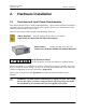
2.2 IFD IF Digitizer Module Installation
The IFD mains power is to be permanently “hard wired” in a NEMA electrical
enclosure that is accessible only to a trained technician. The ground (earth)
connection should be attached directly to the IFD case mounting screw then
brought to the power supply ground connection.
Disconnect the the mains power before opening the IFD for service. The IFD is
best serviced by disconnecting the mains power, removing it from its mount and
placing it on a bench.
2.2.1 IFD Introduction
The IFD IF digitizer is housed in an electrically sealed solid metal enclosure to achieve good
immunity to external electrical noise. The internal circuitry has been designed to minimize the
number of digital components, and it is carefully grounded and shielded to make the cleanest
possible samples of the input IF signal. The unit is cooled by direct conduction of heat through
the metal chassis; there are no openings required for airflow.
The IFD replaces all of the IF receiver components that are found in a traditional analog receiver
system, i.e.,
S Band Pass Filters
S LOG Receiver
S AFC Circuit
S AGC or IAGC circuit
S Quad Phase Detector
S COHO (on magnetron systems)
S Line drivers for base band video
Indeed, one of the most time consuming parts of an upgrade is often the removal of old
components. Many customers choose to simply bypass them and leave them in place. In some
cases there will be other receiver modifications required to match the IFD signal input
specifications. For example, IF attenuators or an IF amplifier are sometimes required.
If you are doing an upgrade of an older system, you might want to consider
purchase of a new STALO which can make significant improvements in Doppler
performance.
You should carefully document and red-line your system schematics to reflect any changes to the
receiver.