
Installation Instructions

Hardware Installation
RVP8 User’s Manual
September 2005
2–4
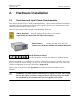
2.2.3 IFD Power, Size and Mounting Considerations
The IFD is a compact sealed module with dimensions 23.6 x 10.9 x 3.0 cm. (9.3 x 4.3 x 1.2 in).
The unit is designed to be mounted on edge such that the 23.6 x 3.0 cm. surface is flush on the
back of the receiver cabinet with 10.9 cm. protrusion into the cabinet. The unit is typically
placed where a traditional LOG receiver would be installed. The IFD is cooled by direct
conduction through its metal enclosure. It should be positioned so that air can freely convect
around it, or bolted to a larger surface that will conduct the heat away.
The power supply module is separate and can be mounted nearby in the radar cabinet, or it can
be attached directly to the IFD using a special mounting bracket. The power supply and bracket
will add 3.3 cm. (1.3 in) of overall width to the receiver module.
The power supply is a low noise, low ripple, switching unit; the input voltage range is 100–240
VAC 47–63 Hz, autoranging. The IFD has an internal 3-stage power supply input filter to
minimize interference from the power cable. Nonetheless, it is still good practice to insure that
the four supply wires (+5V, –12V, +12V, and Ground) be kept short and twisted together. A
ferrite choke around the supply wires near the terminal strip is also recommended.
Important: The inductive filtering components inside the IFD introduce a
voltage drop in the +5V supply. To produce the correct internal voltage, the
supply voltage measured at the external terminal block should be 5.33V for
Rev.E and later, 5.23V for Rev.D, and 5.17V for Rev.C and earlier boards.
Important: The voltage drop across the inductive filtering components causes
the ground terminal of the power supply to float several tenths of a volt above
chassis ground. For this reason, the IFD power supply should never be tapped
to supply power to other nearby equipment.
Mounting space should also be reserved for the external analog anti-alias filters. These filters
can be mounted in the radar cabinet itself, or they can be attached directly to the IFD on the
opposite side of the power supply. The filters and mounting bracket will add 2.0 cm. (0.8 in) of
overall width.
The 72MHz CAT-5E IFD (Rev.F) represents a factor–of–two improvement in A/D sampling rate
and communications bandwidth between the IFD and RVP8/Rx card. This provides important
advantages in the performance of your radar system, but it does also place greater demands on
the connecting link. The CAT-5E cable carries real–time 1.080MBaud downlink serial data on
three of its four twisted pairs, and uses the fourth pair for uplink communication. The data rate
on each downlink pair actually exceeds the data rate for GigaBit ethernet, hence very high
quality cable must be used, and maximum cable length is limited to 25-meters. There is also a
minimum cable length of 2-meters.
We recommend using a shielded CAT–5E cable (certified to >= 350MHz) having shielded RJ45
plugs on each end. The Rx board provides a DC return path for the cable shield, while the IFD
provides an AC GND only (isolated to 2KV). This design prevents ground loop currents from
flowing between units, even when they’re plugged into different AC/Mains.