
Installation Instructions

Hardware Installation
RVP8 User’s Manual
September 2005
2–6
2.2.5 IFD Adjustments and Test/Status Indicators
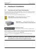
The IFD is packaged in a tight metal enclosure for maximum noise immunity. The only
adjustments on the module are the internal gain and offset pots that adjust the AFC analog
output. Two switches on the unit provide standalone test features to verify the proper functioning
of the IFD and to assist with setting the voltage span of the AFC DAC.
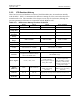
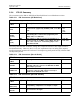
Table 2–5: IFD Toggle Switch Settings
SW1 SW2 Function
A A AFC Test Low Voltage
A B AFC Test Midpoint Voltage
A C AFC Test High Voltage
B A Swap Burst and IF Input Signals
B B Normal Operation (also labeled as “run”)
B C Reserved (downlink test pattern)
C A Reserved
C B Reserved (downlink test pattern)
C C Reserved (downlink test pattern)
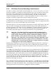
Two LEDs provide status information for the IFD itself, as well as status of the communication
link(s) to the RVP8/Rx PCI card. These LEDs have the same interpretation across all revisions
of the IFD. For Rev.B through Rev.D the words “uplink” and “downlink” refer to the physical
coax uplink and fiber downlink cables. For Rev.E and higher, those words refer to conceptually
similar uses of the four twisted pairs within the integrated CAT-5E link.
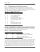
Table 2–6: IFD LED Indicator Interpretations
Red (Uplink) Green (Ready) Meaning
Blink Blink Reset sequence (powerup, or from uplink)
Blink Off Uplink is dead (no uplink protocol from RVP8/Rx)
On Off Uplink is alive, but downlink is dead
On On Normal Operation (IFD and Main are both okay)
For IFDs at Rev.E and higher, the two LEDs on the RJ-45 connector also convey status about the
CAT-5E link itself. Green indicates that valid clock and framing waveforms are present on the
uplink. Yellow indicates that the RVP8/Rx card is receiving valid data from the IFD, including
the IFD’s report of the uplink being okay. These LEDs show valid status at all times (not just
when the RVP8 software is running) and thus, both indicators should be illuminated whenever
the CAT-5E cable is connected. Moreover, the Green/Yellow interpretation is consistent at both
the IFD and RVP8/Rx ends: green indicates the reception of proper low-level electrical and