
Installation Instructions
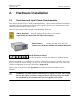

Hardware Installation
RVP8 User’s Manual
September 2005
2–7
framing protocols, and yellow indicates that the green LED is ON at the other end, i.e., that the
other end is receiving our transmissions correctly and is able to communicate that information
back to us.
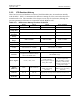
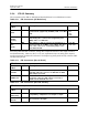
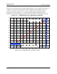
The internal jumper settings are summarized in the following table. Please also refer to Sections
2.2.11 and 2.2.12 for more information on setting up the AFC or External Clock options.
Table 2–7: IFD Internal Jumper Settings
Rev.B Rev.C Rev.D Rev.E and Higher
JP1 N/A
AB: AFC Voltage Output
BC: External Clock Input, 50W Termination
Open: External Clock Input, No Termination
JP2 N/A Reserved (Open)
AB: Normal JTAG control
BC: Factory reserved
JP3 N/A
AB: Unused
BC: External Clock
Open: AFC Voltage Output
Power Supply to Oscillator
Use wirewrap, not jumper
AB: Regulated from +12V
BC: Direct from +5V
JP4 N/A
AB: Dither Applied to Burst
BC: No Dither on Burst
AB: Oscillator is a VCXO
BC: Oscillator is fixed XO
JP5 N/A
Reserved for factory tests
Must be left open
JP6 N/A
J4 Protocol Selector
AB: Legacy DAFC output
BC: Auxiliary CLK In/Out
JP7 N/A
J4 DAFC Output Level
AB: +5V Signaling
BC: +12V Signaling