
Technical Manual


3
F. Hard Tube Modulator Control
G. Solid-State Filament Power Supply
The Modulator section contains the following sections:
A. Switch Driver Assy
B. PRF Driver
C. High Power Switch Section
D. Magnetron Peak Current Detector
The input voltage for the system is 220 VAC single phase and it enters the system
via a connector located in the rear lower panel of the cabinet.
The input line voltage enters the system via a circuit breaker located on the control
panel. The control panel is located on the front upper section of the main cabinet.
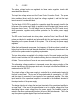
Figure 3.0 shows the mechanical configuration of the system. The front view of
cabinet shows the control panel located on the upper section.
The main electrical system diagram is shown on figure 4.0. The main power is
switched on by the circuit breaker on the control panel and is further fused before
entering the power supply section. It enters the front end of the power supply and is
applied to the power factor correction section.
The Power Factor Correction Module performs the rectification, in-rush current
limiting and preregulation of the input line voltage.
The power factor module provides a preregulated DC Voltage level of 360 VDC. The
above 360 VDC is applied to the input of the series resonance converter which, in
turn, provides a final adjustable level of 0-900 VDC available at the modulator
section.
The above DC output is sent to the modulator section through three of wires leaving
the back of the power supply section. The input PRF, which is TTL level, enters the
control panel and is further processed by the Modulator control circuit.
It enters the Modulator Control Circuit, which transforms this input signal to a
selectable pulse-width level proper for triggering the modulator section of the system.
The modulator control circuit performs additional functions, as will be discussed later
under the Power Supply section.
Figure 5.0 shows the complete power supply section of the system. The power
supply also provides the low voltage bias levels required by the modulator. The
modulator section receives the trigger input from the modulator control circuit located