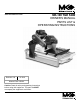
www.mkdiamond.com Revision 102 MK-100 TILE SAW OWNER'S MANUAL PARTS LIST & OPERATING INSTRUCTIONS 12.2012 Manual Part# 158192 Caution: Read all safety and operating instructions before using this equipment. This parts list MUST accompany the equipment at all times.
INTRODUCTION Congratulations on your purchase of a MK-100 Tile Saw. We are certain that you will be pleased with your purchase. MK Diamond takes pride in producing the finest construction power tools and diamond blades in the industry. Operated correctly, your MK-100 Tile Saw should provide you with years of service. In order to help you, we have included this manual. This owners manual contains information necessary to operate and maintain your MK-100 Tile Saw safely and correctly.
TABLE OF CONTENTS SAFETY Safety Messages General Safety Precautions California Proposition 65 Message Hazard Symbols Electrical Requirements Safety Label Locations Product Specifications 4 4-6 6 7 8-10 11 12 UNPACKING, TRANSPORT and ASSEMBLY Unpacking Contents Transport Stand Assembly 13 13 14 15 16-17 SETUP, STARTUP, ADJUSTMENT, OPERATION and SHUTDOWN Setup Operation Cutting Head Adjustment Cleanup 18-20 20-23 24-26 27 MAINTENANCE AND TROUBLESHOOTING Maintenance Troubleshooting 28-33 34 EXPLODED VI
MK-100 Tile Saw Safety Read and follow all safety, operating and maintenance instructions. Failure to read and follow these instructions could result in injury or death to you or others. Failure to read and follow these instructions could also result in damage and/or reduced equipment life. SAFETY MESSAGES A safety message alerts you to potential hazards that could hurt you or others. Each safety message is preceded by a safety alert symbol ( ) and one of three words: DANGER, WARNING, or CAUTION.
MK-100 Tile Saw Safety MAKE THE WORKSHOP KID PROOF Make the workshop kid proof by using padlocks, master switches or by removing starter keys. DO NOT FORCE THE TOOL A power tool will do a job better and safer operating at the rate for which it was designed. USE THE RIGHT TOOL DO NOT force a tool or an attachment to do a job that it was not designed to do. USE THE PROPER EXTENSION CORD If using an extension cord make sure it is in good condition first.
MK-100 Tile Saw Safety USE RECOMMENDED ACCESSORIES Consult the owner’s manual for recommended accessories. Using improper accessories may increase the risk of personal or by-stander injury. NEVER STAND ON THE TOOL Serious injury could occur if a power tool is tipped, or if a cutting tool is unintentionally contacted. CHECK FOR DAMAGED PARTS Before using a power tool, check for damaged part.
MK-100 Tile Saw Safety SILICA DUST WARNING Grinding/cutting/drilling of masonry, concrete, metal and other materials with silica in their composition may give off dust or mists containing crystalline silica. Silica is a basic component of sand, quartz, brick clay, granite and numerous other minerals and rocks. Repeated and/or substantial inhalation of airborne crystalline silica can cause serious or fatal respiratory diseases, including silicosis.
MK-100 Tile Saw Safety ELECTRICAL REQUIREMENTS AND GROUNDING INSTRUCTIONS In order to prevent potential electrical shock and injury, the following electrical safety precautions and symbols should be followed at all times! WARNING In case of a malfunction or breakdown, grounding provides a path of least resistance for electric current to reduce the risk of electric shock. This tool is equipped with an electric cord having an equipment-grounding conductor and a grounding plug.
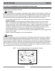
MK-100 Tile Saw Safety WARNING To avoid the possibility of the appliance plug or receptacle getting wet, position the machine to one side of a wall mounted receptacle. This will prevent water from dripping onto the receptacle or plug. A “drip loop,” shown in the picture below, should be arranged by the user to properly position the power cord relative to the power source. The “drip loop” is that part of the cord below the level of the receptacle, or the connector, if an extension cord is used.
MK-100 Tile Saw Safety WARNING To reduce the risk of electrocution, keep all connections dry and off the ground. Do not touch the plug with wet hands. WARNING Use of under sized extension cords result in low voltage to the motor that can result in motor burnout and premature failure. MK Diamond warns that equipment returned to us showing signs of being run in a low voltage condition, through the use of undersized extension cords will be repaired or replaced totally at the customer's expense.
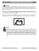
MK-100 Tile Saw Safety SAFETY LABEL LOCATIONS Safety labels contain important safety information. Please read the information contained on each safety label. These labels are considered a permanent part of your saw. If a label comes off or becomes hard to read, contact MK Diamond or your dealer for a replacement. D ! WARNING A C For Your Own Safety Read Instruction Manual Before Operating Saw. Wear Eye Protection. Disconnect Saw Before Servicing, when Changing Cutting Wheels and Cleaning.
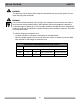
MK-100 Tile Saw product specifications PRODUCT SPECIFICATIONS The MK-100 is a versatile Tile Saw. Operated and used according to this manual, the MK-100 will provide years of dependable service. General Description The MK-100 Tile Saw is engineered as a tabletop or stand mounted wet tile saw. The saw includes a powerful 120V electric motor. The saw is capable of cutting tile up to twenty (20) inches in length, depth of cut 3". Motor Specifications Motor specifications for the MK-100 are listed in below.
MK-100 Tile Saw content UNPACKING Your MK-100 has been shipped from the factory thoroughly inspected. Only minimal assembly is required. CAUTION Use proper lifting techniques when lifting the MK-100. If not done, remove the MK-100, Cutting Head and accessory box from the carton.
MK-100 Tile Saw TRANSPORT TRANSPORT CAUTION 1. The MK-100 weighs approximately ninety-six (96) pounds; use care when transporting. 2. Never transport the MK-100 with water in the Water Pan. The MK-100 is designed with a rigid frame and removable Cutting Head. Two people are required to transport the MK-100 with the Cutting Head installed. The Cutting Head must be removed first, if one person is transporting the saw (see Cutting Head Installation and Removal in the following section).
MK-100 Tile Saw STAND FOLDING STAND CAUTION The MK-100 weighs ninety-six (96) pounds; follow the guidelines in the TRANSPORT section when placing it on the stand (MK Diamond Part# 168244). Note: If using the Optional MK Diamond Stand, follow these steps. (A) Open the stand and place on flat surface. Remove Water Basin from saw. (B) Place saw on stand. (C) Ensure saw frame is positioned properly. (D) Reinstall the Water Basin.
MK-100 Tile Saw ASSEMBLY ASSEMBLY Follow the assembly instructions to prepare your MK-100 for operation. CUTTING HEAD INSTALLATION Note: If the Cutting Head is installed, go to the next step. (A) Align Cutting Head Rear Pivot Hole to the Post Pivot Shaft and slide onto shaft. (B) Secure the Cutting Head by installing the Adjusting Knob. DIAMOND BLADE INSTALLATION Note: When installing the Retaining Nut, do not "cross-thread" and DO NOT over tighten the nut.
MK-100 Tile Saw ASSEMBLY ADJUSTABLE CUTTING GUIDE INSTALLATION Note: The Adjustable Cutting Guide can be used on either side of the Diamond Blade. (A) Loosen Adjustable Cutting Guide retaining thumbscrew and place it over the Movable Cutting Table Ruler/Stop. (B) Place the Adjustable Cutting Guide onto the Movable Cutting Table Ruler/Stop and tighten the retaining thumbscrew.
MK-100 TILE SAW SETUP PRE-START INSPECTION Prior to beginning work, a pre-start inspection of the saw should be performed. (A) Ensure the ON/OFF Switch is in the OFF position. (B) Verify the Movable Cutting Table moves freely. (D) Inspect the Pump Assembly for damage. Ensure the cord is free of cracks or cuts. (E) Inspect the MK-100 for damage. Ensure the cord is free of cracks or cuts. 18 (C) Inspect the Diamond Blade for damage. Verify the blade is correct for the material being cut.
MK-100 TILE SAW SETUP CONNECTING WATER PUMP WARNING To prevent the possibility of electrical shock, the MK-100 MUST be de-energized when connecting the Water Pump. To prevent the possibility of electrical shock, use only MK Diamond qualified replacement parts. Note: To prevent pump damage, the Water Pump must be disconnected from its power supply if cutting with a Dry Blade. (A) Connect the Cooling Transfer Tube to the inlet connection of the Blade Guard.
MK-100 SETUP RE-CIRCULATION NOTE: When using the re-circulation method, the water should be changed often for longer pump life. (A) Ensure the Drain Plug is installed in the Water Basin. NOTE: (B) Place the Water Pump in the back of the Water Basin. Ensure the power cord and cooling tube exit the water basin under the top rail of the frame.
MK-100 OPERATION PORTABLE GENERATOR If using a portable generator to provide power, ensure the generator meets the following minimum requirements: 8Kw 120 Volts 20 Amps Single Phase GROUND FAULT INTERRUPTER Ground Fault Interrupters (GFCI) provide protection from the dangers of electrical hazards. Receptacles are available having built-in GFCI protection and may be used for this measure of safety. Otherwise a GFCI should be used. (A) Ensure the ON/OFF Switch is in the OFF position.
MK-100 OPERATION Cutting Straight Edges CAUTION DO NOT FORCE THE TOOL. It will do the job better and safer at the rate for which it was designed. (A) Loosen the Adjustable Cutting Guide retaining thumbscrew. (D) Verify proper cooling flow on both sides of the blade (See Maintenance Section to increase/decrease flow). (B) Position the Adjustable Cutting Guide to desired cut length indicated inside the diamond and tighten. (C) Place the tile against the Ruler/ Stop and Cutting Guide.
MK-100 OPERATION (D) Perform the cut. Turn the motor OFF when work is complete. 45° Miter Cutting CAUTION DO NOT FORCE THE TOOL. It will do the job better and safer at the rate for which it was designed. NOTE: To cut 45° Miters, the 45° Bullnose Miter Guide should be used (MK Diamond Part # 134585-MK). (A) Position the 45° Bullnose Miter Guide and tighten the retaining thumbscrews. (B) Position the tile on the 45° Bullnose Miter Guide and the Ruler/Stop. Turn on the motor.
MK-100 OPERATION Off-angle Cutting Note: CAUTION To cut angles other than 45° angles or Miter, a 90° Protractor (MK Diamond Part No. 134569-MK) should be used. DO NOT FORCE THE TOOL. It will do the job better and safer at the rate for which it was designed. (A) Place the 90° Protractor on the Ruler/Stop and tighten the retaining thumbscrew. (D) Verify proper cooling flow on both sides of the blade (See Maintenance Section to increase/decrease flow).
MK-100 CUTTING HEAD ADJUSTMENT Adjusting the Cutting Head CAUTION The Cutting Head is heavy. When loosening the Cutting Head Adjustment Knob, the Cutting Head will pivot down unless held. Care must be used when changing the position of the Cutting Head. (A) Remove the blade. Support the Cutting Head and then remove Adjusting Knob. (D) Install the Cutting Head onto the front pivot hole. (B) Remove the Cutting Head from the rear pivot hole. (C) Move Cutting Head Stop to down position.
MK-100 CUTTING HEAD ADJUSTMENT Adjusting the Motor Post for Maximum Cutting Length CAUTION The Cutting Head and Motor Post are heavy. Care must be used when changing the position of the Cutting Head. NOTE: Do not unscrew the Motor Post Retaining Bolts completely. There is a Stand Off that needs to be removed with the Retaining Bolts. (A) Remove Water Basin and Blade. Secure the Cutting Head and then remove Adjusting Knob. (B) Remove the Cutting Head (Cutting Head Adjustment pg 25).
MK-100 CLEANUP CLEANUP NOTE: If an external water source was used, steps A through C may be skipped. Dispose of waste water in accordance with applicable Federal, State and Local laws. (A) Clean the Water Pump suction of all debris (B) Place the Water Pump in an external container (C) Run the MK-100 until clear water is seen at the blade cooling ports (Approx. 1 min.) (D) Remove the Water Basin and clean.
MK-100 MAINTENANCE MAINTENANCE Perform the following after initial purchase and operation of the MK-100. Maintenance Following Use To extend the life of the MK-100, the following procedure should be performed after each use. Lubricate all points listed below with light oils such as, 3 in 1, WD-40, etc. (A) Lubricate the Guide Bar. (B) Lubricate the Roller Wheel Assembly. Monthly Maintenance The following maintenance should be performed monthly. (A) Remove the Diamond Blade.
MK-100 MAINTENANCE Monthly Maintenance Cont. (G) Remove the Blade Guard. Lubricate the Blade Guard Pivot Shaft. (H) Remove the Cutting Head (Cutting Head Adjustment pg 25). (J) Lubricate the Cutting Head Adjustment Knob retaining holes. (K) Lubricate the Cutting Head Pivot Shaft. (I) Lubricate the threads on the Cutting Head Adjustment Knob. Flow Adjustment NOTE: If flow to the diamond blade requires adjustment, perform the following actions.
MK-100 MAINTENANCE Blade Dressing Like most cutting instruments, a diamond blade performs best when it is dressed. Over time and use, diamonds on the outer edge of the blade may become smoothed or "glazed" over. This will reduce grinding efficiency and may cause the blade to "wander" or bend giving the illusion of an alignment problem. When this occurs, the blade will need to be dressed.
MK-100 MAINTENANCE V-Belt Inspection, Adjustment and Replacement The MK-100 is designed with power transmission Micro-V Belt. In order to ensure the MK-100 operates a peak efficiency, the Micro-V Belt should be inspected monthly, and changed if the Micro-V Belt shows damage and/or excessive wear. NOTE: When a new belt is installed, it should be inspected and re-tensioned after the first forty-eight (48) hours of operation. (A) Remove the Diamond Blade.
MK-100 MAINTENANCE (J) Push the motor toward the front of the Cutting Head to loosen the V-Belt. (K) Remove the V-Belt. (L) Install the new V-Belt (MK Diamond Part No. 158194). (M) Verify the V-Belt is seated in the grooves of both pulleys. (N) Tighten the Motor Adjustment Strap to remove slack. (O) Check V-Belt tension (proper tension 1/8-inch) Repeat steps N and O until proper Micro-V Belt tension is achieved. (P) Tighten the four motor mounting bolts. (Q) Install the Belt Guard.
MK-100 MAINTENANCE Cooling Flow (A) Check cooling flow Adjusting Clamp open. (B) Remove the Cooling Transfer Tube from the Blade Guard inlet. (C) Place Pump into a bucket of water and check flow. (D) Remove the Cooling Transfer Tube and check flow. (E) Inspect and clean pump. See Pump Manual. (F) Remove the Blade Guard Intake Fitting and check.
MK-100 TROUBLESHOOTING Movable Cutting Table Does Not Move Correctly (A) Check that the Guide Bar is clean - clean if dirty. (B) Check the Movable Cutting table Roller Wheels for wear, replace if necessary. Blade will not cut properly (A) Check for smoothness or "Glazing" (See Blade Dressing Section) Blade Stops Turning (A) Allow motor to cool and depress motor Overload Reset Switch. NOTE: (B) Check for proper blade rotation.
NOTES 35
MK-100 Exploded view 36
MK-100 Item parts list Part# Description Qty Wrench, 15/16 Closed End curtain, splash bracket, splash curtain wingscrew, 1/4 - 20 x 1/2 washer, 1/4 sae flat pump, 115V water FITTING, PLASTIC, 1/4 FNPT X 1/4 BARB HOSE, VINYL, 1/4 ID CLAMP, FLOW, 1/4 - 1/2 owner's manual, water Pump rip guide BLADE, MK-100, 10 X .
MK-100 Item parts list Part# Description Qty SCREW, HEX HEAD (NOT SHOWN) BLADE GUARD, 110/115 ELBOW, 1/8 MNPT X 1/4 BARB 90° BRASS TUBE, WATER SCREW, 5/16 - 18 X 1/2 SOCKET HEAD SET LABEL, TILE SAW SERIAL NUMBER 1 1 1 2 3 1 n/a 162473 162481 154652 155389 152607 157249-01 SUBASSEMBLY, 115V CUTTING HEAD, MK-100 HEAD, 10" CUTTING PIN, BLADE SHAFT LOCK SPRING, BLADE GUARD LOCK E-RING, 1/4 RETAINING BEARING, 17MM X 40MM X 12MM BALL (6203 - 2NSSE) SHAFT, BLADE 880/101/108FLANGE, 2 - 3/8 INNER FLA
MK-100 Item K-M K K1 K1A K2 K3 K4 ASSEMBLY, TABLE TABLE parts list Description Qty Part# TABLE, 100 BEARING, 3/4 ID MULTILUBE WASHER, 5/16 SAE FLAT WASHER, 5/16 SPLIT LOCK SCREW, 5/16 - 18 X 1 HEX HEAD CAP 1 2 2 2 2 157660 152227 151754 151747 151743 BAR, 3/4 X 32 GUIDE, 101 SCREW, 5/16 - 18 X 1 HEX HEAD CAP WASHER, 5/16 SPLIT LOCK WASHER, 5/16 SAE FLAT 1 2 2 2 N/A 134759 151743 151747 151754 1 1 1 1 1 151756 154021 151799 151914 151915 151893 L L1 L2 L3 L4 GUIDE BAR M M1 M2 M3 M4 M
MK-100 TILE SAW THEORY THEORY OF DIAMOND BLADES Diamond blades do not really cut; they grind the material through friction. Diamond crystals, often visible at the leading edge and sides of the rim/segment, remove material by scratching out particles of hard, dense materials, or by knocking out larger particles of loosely bonded abrasive material. This process eventually cracks or fractures the diamond particle, breaking it down into smaller pieces.
MK-10O TILE SAW ITEM NUMBER 1. 137166 DESCRIPTION MK-200, 10 x 5/8 Arbor Premium grade Diamond Blade for smooth, chip-free cutting on tile. 2. 128074 MK-215, 10 x 5/8 Arbor Supreme grade diamond blade for hard materials 3. 153252 MK-315, 10 x 5/8 Arbor Supreme super hi-rim diamond blade 4. 134577-MK Dual 45° Flat Angle Guide 5. 153201-MK 45° Bullnose Miter 6. 134569-MK 90° Protractor 7. 152792 Dressing Stone 8. 152610 Ground Fault Circuit Interrupter 9.
MK-100 TILE SAW ORDERING & RETURN ORDERING INFORMATION You may order MK Diamond products through your local MK Diamond distributor or, you may order direct from MK Diamond. NOTE: There is a $25.00 minimum order when ordering direct from MK Diamond. All purchases must be made using VISA, MasterCard or American Express.
NOTES 43
MK-100 TILE SAW OWNER'S MANUAL & OPERATING INSTRUCTIONS MK Diamond Products, Inc. 1315 Storm Parkway Torrance, CA 90501 Toll-Free: (800) 421-5830 Phone: (310) 539-5221 Fax: (310) 539-5158 www.mkdiamond.